![[Manufacturer’s Guide 2026] How Can You Optimize UHF RFID Read Range in Metallic Environments?](https://fongwahrfid.net/wp-content/uploads/2025/12/Manufacturers-Guide-2025-1.webp)
Metal surfaces reflect signals and ruin RFID performance. Are you tired of low read rates in your facility? Here is the solution you need.
To optimize UHF RFID read rangee on metal, you must select specialized on-metal tags with proper standoffs, utilize circularly polarized antennas, and calibrate reader power output. Additionally, applying ferrite shielding materials helps eliminate multipath interference for accurate asset tracking.

Many engineers give up when they see heavy steel racks. I used to struggle with this during my early days on the production line. However, stopping here means missing out on high asset visibility. Read on to master these technical solutions.
Why Does Metal Cause Multipath Issues and Interfere with Signal?
Signals bounce unpredictably off metal racks. This chaos destroys data integrity instantly and creates dead zones.
Metal reflects RF waves, causing multipath interference where signals cancel each other out. It also significantly detunes standard tag antennas, drastically reducing the energy transfer needed to wake up the chip.

Understanding the Physics of Interference
To solve a problem, we must first understand the root cause. From my experience as an engineer at Fongwah, metal creates two primary problems: Detuning and Multipath. When you place a standard dipole antenna label flat against a metal sheet, the metal acts as a ground plane. This changes the impedance of the antenna. The result is a mismatch. The chip does not receive enough power to turn on, and you hear zero beeps from your reader.
Furthermore, we must look at the Multipath Effect. When a UHF wave hits metal, it bounces. These reflected waves can collide with the original wave sent by your reader. Sometimes, they combine to make a stronger signal (constructive interference). More often, they cancel each other out (destructive interference). This creates "null points" in your warehouse where no tag can be read, even if it is right in front of the antenna.
Key Interference Factors
| Factor | Description | Impact on RFID |
|---|---|---|
| Eddy Currents | Loops of electrical current induced within the metal. | Counteracts the reader's magnetic field. |
| Reflection | RF waves bouncing off the surface. | Causes signal cancellation (blind spots). |
| Detuning | Alteration of antenna impedance. | Prevents the tag from powering up. |
We must address these physics principles before selecting hardware. If we ignore the wave behavior, even the most expensive reader will fail.
How Do On-Metal Tag Technologies Solve the Detuning Problem?
Standard labels fail immediately on steel beams. You lose assets and money daily using the wrong consumables.
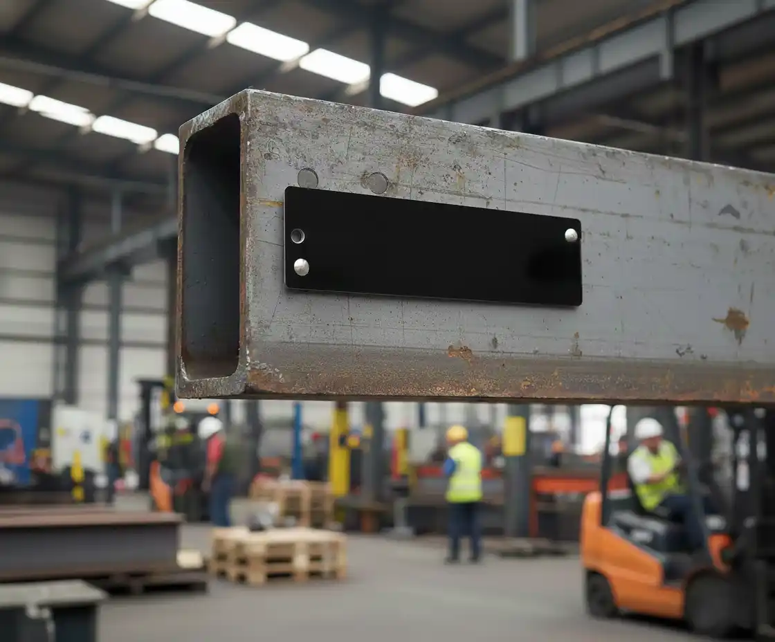
On-metal tags use a spacer or special dielectric materials to isolate the antenna from the metal surface. This restores the tag's impedance match and allows the customized antenna to function correctly.
Selecting the Right Tag Technology
I always tell my clients: the tag is the most critical part of the system. In metallic environments, a standard sticker is useless. You need "On-Metal Tags." These tags are designed with a specific "standoff distance." This is a gap created by a dielectric material that lifts the antenna away from the metal. This gap prevents the metal from shorting out the antenna's electrical field.
At Fongwah, we have tested dozens of materials. Hard substrates like Ceramic or PCB (Printed Circuit Board) are very durable. They work best for industrial assets like molds or containers. For curved surfaces, like pipes, flexible on-metal labels are better. These use a thick foam layer as the spacer.
Tag Selection Guide
| Tag Type | Standoff Material | Best Use Case | Cost Level |
|---|---|---|---|
| PCB Tag | Epoxy / Fiberglass | Heavy Machinery, Tool Tracking | Medium |
| Ceramic Tag | Ceramic | High Heat, Small Tools | High |
| Flexible Label | Synthetic Foam | Curved Cylinder, IT Assets | Low |
When you choose the tag, look at the datasheets. Ensure the "Read Range on Metal" meets your needs. A tag that reads 10 meters in air might only read 4 meters on metal if the design is poor.
What Role Do Antenna Deployment and Polarization Play in Optimization?
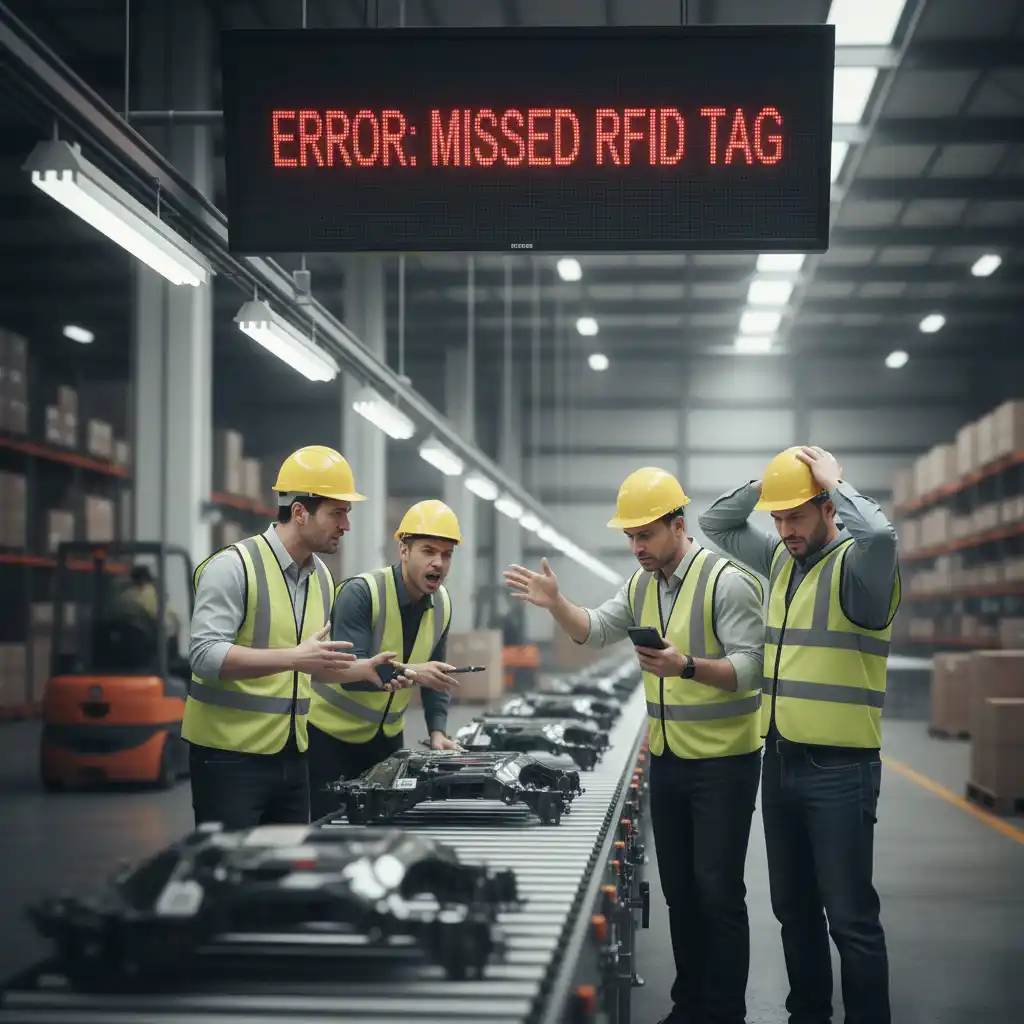
Wrong angles create blind spots in your facility. Missed scans stop production lines and frustrate your team.
Using circular polarization helps capture reflected signals that change orientation. Tilting antennas and using beam forming techniques focus the RF energy exactly where the metal assets are located.
Advanced Antenna Strategies
During my time installing systems, I learned that antenna placement is an art. In a metal-heavy environment, Linear Polarization is risky. Linear antennas send waves in one flat plane. If the wave hits metal and rotates, the antenna cannot "see" the return signal. This is why I recommend Circular Polarization antennas for warehouse environments. They send waves in a spiral. They are much more likely to catch the messy, reflected signals bouncing off your metal shelves.
We must also discuss the "Tilt Angle." Never point an antenna directly perpendicular to a flat metal wall. The wave will bounce straight back and hit the reader, causing high noise. Instead, tilt the antenna at a 30 to 45-degree angle. This deflects the signal away from the source, reducing self-interference.
Polarization Comparison
| Feature | Linear Polarization | Circular Polarization |
|---|---|---|
| Beam Shape | Flat plane (Laser-like focus) | Spiral (Corkscrew shape) |
| Metal Performance | Poor (Sensitive to orientation) | Excellent (Captures reflections) |
| Range | Longer (if aligned perfectly) | Shorter (but more consistent) |
By optimizing the angle and polarization, we stabilize the RF field. This ensures that the reader picks up the tag data, not just static noise.
How Can Reader Calibration and Power Output Tuning Fix Interference?
Max power is not always the answer. It often causes cross-reads and errors in dense environments.
You must adjust the Equivalent Isotropically Radiated Power (EIRP) to balance range and reflection. Utilizing frequency hopping allows the reader to find clear channels amidst the RF noise caused by metal.

Fine-Tuning Your Hardware
A common mistake I see is cranking the reader power to the maximum (usually 30dBm or 33dBm). In a metallic room, this creates a storm of reflections. You will read tags three aisles away but miss the one right in front of you. This is also known as "cross-reading."
At Fongwah, we advise a "Less is More" approach. Start with a lower power setting, perhaps 20dBm. Slowly increase it until you get a reliable read on your target zone. Stop there. Do not go higher. We also use "Frequency Hopping" (FHSS). Metals can block specific frequencies. By hopping between channels (e.g., 902 MHz to 928 MHz), the reader can avoid "dead" frequencies where interference is worst.
Calibration Parameters
| Parameter | Definition | Action Strategy |
|---|---|---|
| Output Power | Signal strength (dBm). | Reduce to limit uncontrolled reflections. |
| Q-Value | Algorithm for collision. | Increase in high-tag-density areas. |
| RSSI Filter | Signal strength threshold. | Set a min value to ignore distant reads. |
By adjusting these software settings, you make the reader "smarter." It stops fighting the metal and starts working around it.
What Are Effective Shielding Strategies for High-Density Metal Areas?
Dense server racks make standard scanning impossible. Signals mix and confuse the system, leading to failure.
Apply ferrite sheets and absorber materials behind antennas or between tags and metal. This absorbs stray energy and creates a localized Faraday cage effect to isolate specific read zones.

Isolating the Signal with Shielding
Sometimes, software and tags are not enough. You need physical barriers. This is common in IT asset tracking within server racks. If you have fifty servers packed with metal parts, the reader gets overwhelmed. The solution is RF Shielding.
We use Ferrite Sheets. These are thin, magnetic sheets that absorb RF energy instead of reflecting it. You can place these sheets behind the RFID antenna. This prevents back-scatter. You can also place them between storage bins. This creates a "Faraday Cage Effect" for each bin. It ensures that when you scan Bin A, you only read tags in Bin A, not Bin B.
Shielding Materials Breakdown
| Material | Function | Application |
|---|---|---|
| Ferrite Sheet | Absorbs high-freq magnetic flux. | Under tags or behind antennas. |
| Aluminum Foil | Blocks and reflects RF completely. | Creates walls between zones. |
| RF Absorber Foam | Dampens signal energy. | Lining the inside of reading tunnels. |
Using these materials requires patience during installation. However, the result is a clean, isolated read zone, even in the most difficult metal environments.
How Did We Achieve 99% Read Accuracy in Warehouse Shelving?
A client nearly fired us over low inventory accuracy. We had to fix it fast or lose the contract.
We combined flexible on-metal tags1 with circularly polarized antennas tilted at 30 degrees. This specific setup overcame the heavy steel racking shelving effects and boosted read rates to near perfection.

Real-World Success Story
I want to share a story about a project in an automotive parts warehouse. The client stored engine parts on massive galvanized steel racks. Initially, they used cheap paper labels and a handheld reader. The accuracy was only 60%. They were losing parts and wasting hours on manual counts. They were frustrated and skeptical about RFID.
I went to the site. First, I replaced the paper labels with Fongwah's Flexible On-Metal Tags. These have a 2mm foam standoff. Next, we installed fixed readers on the forklifts. We did not aim them straight. We angled the antennas down at 30 degrees towards the pallets. Finally, I tuned the reader power down to 27dBm to stop reflections from the ceiling.
Project Results
| Metric | Before Optimization | After Optimization |
|---|---|---|
| Read Rate | 60% (Unreliable) | 99.2% (High Accuracy) |
| Inventory Time | 4 Hours | 20 Minutes |
| Tag Type | Standard Paper Label | Flexible On-Metal Foam Tag |
The result changed their operations. They went from daily chaos to smooth, automated tracking. This proves that with the right combination of physics, hardware, and calibration, metal is not a barrier.
Conclusion
Metal environments are tough, but using on-metal tags, circular polarization, and shielding solves the problem. Trust Fongwah for quality tools and advice.
---Discover the unique features of on-metal tags and how they can improve RFID performance on metal surfaces. ↩