Missed scans in a large deployment rarely trace to the reader chip. They trace to the antennas: their polarization, their gain, their placement, and how several of them phase together. The reader is only as good as the field its antennas paint. Antenna planning, not reader firmware, decides whether a gate reads at 99 percent or 70 percent.
RFID reader antennas decide large-scale performance because polarization sets what gets read, gain sets how far the field reaches, placement geometry sets where the field is clean, and multi-antenna phasing sets how completely a zone is covered. Treat antennas as the system, not as accessories, and deployment performance follows.
Most buyers spec the reader and treat antennas as an afterthought, then wonder why the gate misses tags. The pillar RFID reader buying guide puts reader class first, but antenna choice is the lever that actually moves read rate at scale. For the supply-chain view, see why high-performance UHF readers are the backbone of modern supply chains.
How does antenna polarization change what gets read?
A tag is a dipole, and a dipole only couples to the field component parallel to it. Orientation is not optional in the real world.
Linear polarization reads only tags aligned to its axis and creates blind spots for orthogonal tags, while circular polarization reads tags at any rotation, which is why circular is the default for mixed-orientation freight.
On a conveyor where every carton is presented the same way, a linear antenna aimed at the tag plane is efficient and cheap. In a receiving dock where pallets arrive turned every which way, linear polarization will miss a meaningful share of tags no matter how much power you add. Circular polarization costs about 3 dB of link budget but removes the orientation dependency, and at scale that trade pays for itself in first-pass reads. The range troubleshooting checklist often finds polarization mismatch hiding behind what looks like a power problem.
What does antenna gain in dBi actually buy you?
Gain is not magic range. It is the shaping of radiated energy into a narrower, stronger beam.
Higher gain, measured in dBi, concentrates the field into a tighter beam so you reach farther in that direction, but it narrows the coverage angle, so gain must be matched to the read-zone shape rather than maximized.
A 6 dBi antenna gives a fat, forgiving pattern good for a wide gate. A 9 dBi antenna throws the field farther but into a narrower cone, ideal for a long aisle but poor for a wide portal. Picking the highest gain because it sounds best is a classic error: you get range you cannot use and blind spots at the edges. The components of an RFID reader include the RF front end, but the antenna gain is what the front end's power actually becomes in space.
Cable loss eats gain before it leaves the reader. A 3 dB cable loss halves your effective radiated power, so a high-gain antenna on a long cheap cable can perform worse than a modest antenna on short low-loss cable. Budget the link, do not trust the antenna label. As a practical number, a 6 dBi panel at 30 dBm might give a 4 m wide and 6 m deep gate, while a 9 dBi panel stretches depth to 9 m but narrows width to 2.5 m. Neither is better; they answer different openings.

Why does far-field placement geometry beat raw power?
The instinct under a missed read is to raise power. Geometry usually fixes more than power does.
Far-field placement geometry, the distance and angle between antenna and tag relative to the antenna's near-field and far-field boundary, determines whether the tag sits in a clean radiating region, and correct geometry recovers reads that extra power cannot.
Every antenna has a near-field region close to the element where the field is reactive and unpredictable, and a far-field region where it is a clean traveling wave. Placing a tag too close to the antenna, inside the near field, can actually reduce reads because the field is not yet formed. Moving the tag into the far field, at the designed distance, often solves a "weak reader" complaint with no power change. A useful rule of thumb sizes the near-field boundary at roughly r equals 2 times D squared divided by lambda, where D is the largest antenna dimension. For a 15 cm patch operating at 915 MHz that boundary sits about 15 cm from the element, so a tag pressed flat against the face is inside the reactive region and reads worse than one held a few centimeters out. Knowing that distance turns "move it around until it works" into a measured placement decision.
This is why a site survey that maps near-field and far-field boundaries beats a blanket power bump, and why the range troubleshooting guide starts with environment before firmware.
How does beam width shape a read zone?
Beam width is the angular spread of useful field, and it decides whether one antenna covers a zone or creates gaps at the sides.
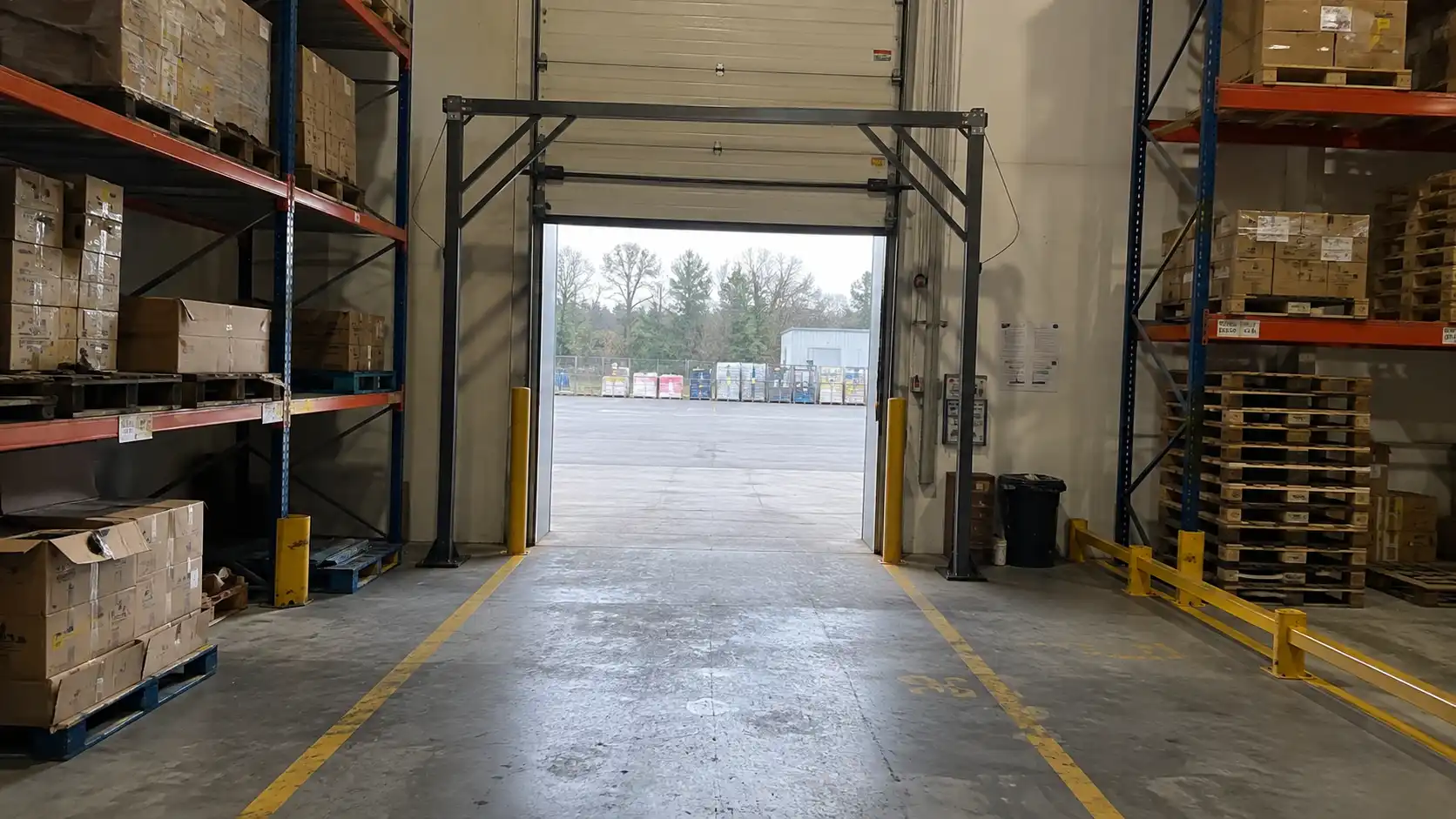
Beam width sets the footprint of the read zone for a given mount distance, so a wide beam covers a broad gate while a narrow beam confines reads to a lane and prevents cross-reads into adjacent aisles.
At a wide shipping gate you want a broad beam so a tag anywhere across the opening is caught. At a narrow lane between two aisles you want a tight beam so the reader does not also catch tags on the next lane, which would corrupt inventory counts. Beam width and gain are linked: higher gain narrows the beam. Choose them together against the physical opening. Mounting height and downtilt then position that beam where the tags actually travel, not where the ceiling is.
What does multi-antenna phasing do for coverage?
One antenna leaves nulls. Physics guarantees it, because reflected waves cancel in spots.
Multi-antenna phasing places several antennas at different physical positions with coordinated timing so their fields overlap and fill the nulls that any single antenna creates, raising detection probability across a zone.
Radio reflects off metal and concrete, and in some spots the direct and reflected waves cancel, leaving a tag invisible to one antenna. A second or third antenna, positioned away, sees a different path and reads that tag. This spatial diversity is why a 4-antenna gate outperforms one high-gain antenna for irregular freight. Phasing is not just more boxes; it is coordinating dwell time and position so the zones overlap deliberately rather than fight each other. At building scale the same principle decides whether a multi-reader rollout reads cleanly or leaves shadowed aisles that quietly drain accuracy.

Conclusion
Antennas are the system that decides large-scale RFID performance. Match polarization to tag orientation, gain and beam width to the zone shape, placement to the far-field boundary, and use multiple phased antennas to erase nulls. Power is the last lever, not the first.
For a multi-reader, multi-antenna rollout, Contact Fongwah to start a technical review of your site layout, port counts, cable runs, and antenna classes.
Q: When should I use linear versus circular polarization?
A: Use linear when tags are presented at a known, consistent orientation, such as a fixed conveyor face. Use circular for mixed-orientation freight like pallets at a receiving dock, because it reads tags at any rotation despite a roughly 3 dB link penalty.
Q: Does higher antenna gain always mean longer read range?
A: No. Higher gain in dBi concentrates the field into a narrower beam. It reaches farther in that direction but shrinks the coverage angle, so a too-high gain can create edge blind spots at a wide gate. Match gain to the zone shape.
Q: Why does antenna placement matter more than power?
A: Every antenna has a near-field region where the field is reactive and unpredictable. A tag placed inside it may read poorly no matter the power. Moving the tag into the far-field, clean radiating region often fixes reads without raising power.
Q: How do multiple antennas improve coverage?
A: Radio reflects off surfaces and cancels in spots, leaving nulls a single antenna cannot fill. Several antennas at different positions with coordinated timing overlap their fields and erase those nulls, raising detection probability across the zone.