RFID article sharing

Multi-Channel UHF RFID Architecture for Dense Tabletop Token Tracking

By fongwah2005@gmail.com
13 min read
Multi-Channel UHF RFID Architecture for Dense Tabletop Token Tracking

A desktop automation cell lost ~20% of its tag reads while polling four localized antenna zones across stacked token tags. The single-channel reader paired with a manual DIY RF switch produced immediate signal lockups and dropped entire tag populations during local polling. This postmortem explains the multiport fix.

The failure above is a classic symptom of applying single-reader topology to a problem that demands a true multiport architecture. For engineers evaluating this class of system, understanding what RAIN RFID is is the baseline: UHF passive tags backscatter modulated energy from an interrogator, and the physics of that exchange break down the moment you stack dozens of thin tags within inches of each other. Our broader RFID reader buying guide frames when a native multiport module — not a switched single channel — is the correct architectural call. This article goes one layer deeper, into the RF hardware causes behind the postmortem telemetry.

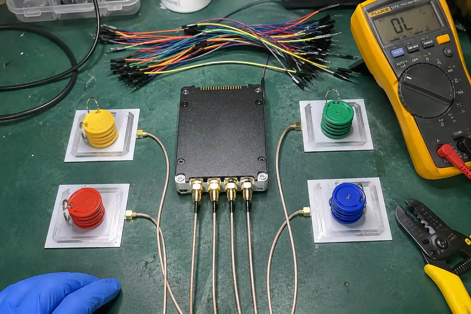
Multiport UHF RFID reader cycling four antenna zones across a tabletop token tracking cell via time-division multiplexing

The Engineering Reality of Multiplexing UHF RFID Antenna Arrays

Key Takeaway: A single-channel reader sequentially polling four spatially separated antenna zones cannot preserve per-port dwell time or a clean baseband decode window when switching occurs outside the native RF PHY. The micro-hardware root cause is baseband packet preamble corruption combined with insufficient port-to-port isolation under external RF switching.

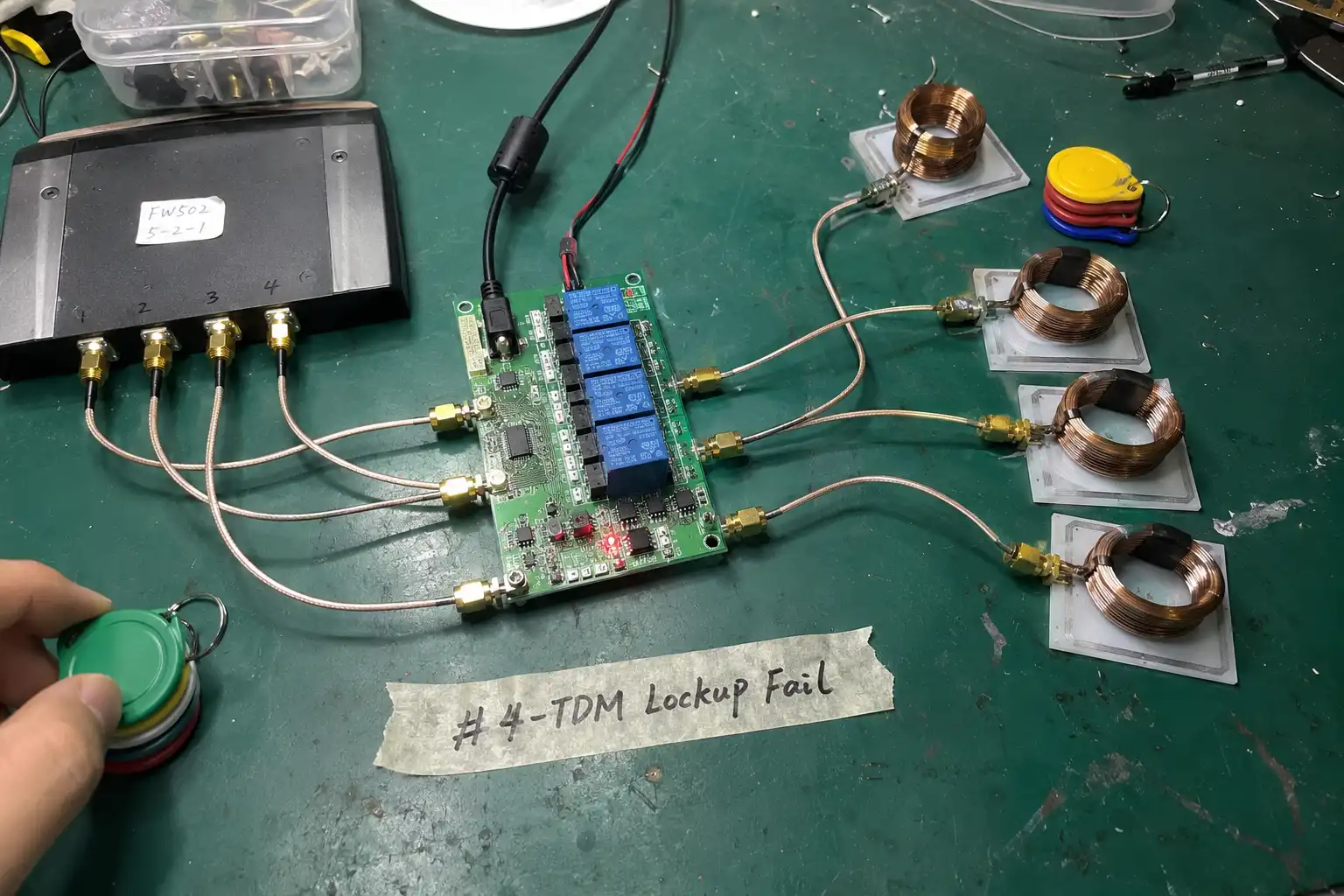
Four-zone UHF RFID antenna array wired through a hand-built RF switch, with electromagnetically coupled port regions highlighted

Time-division multiplexing (TDM) is the conventional method for servicing multiple antenna ports from one shared RF front end. The reader grants each port a dwell window, energizes the field, captures backscatter, then hands off to the next port in the sequence. On paper this looks like an economical way to cover four localized zones with a single radio and a single bill of materials. In the postmortem cell, that assumption collapsed under load.

The desktop automation system routed four antenna nodes — spaced less than 18 inches apart — into a single-channel UHF interrogator through a hand-built RF switch. During local polling the reader reported immediate signal lockups and dropped entire tag populations. The measured ~20% aggregate miss rate clustered in the zones where two or more ports sat electromagnetically coupled. Because the port switching happened outside the reader's native physical layer, the baseband controller never observed a clean handoff between zones. Preambles arrived inside a corrupted decode window, and the MAC layer could not recover them before the next dwell began.

This is the same parasitic-coupling failure class documented in handheld encoding failures from parasitic coupling, where unmanaged near-field interaction between adjacent coils corrupts tag initialization. On a tabletop token cell the difference is population scale: you are not initializing one tag at a time, you are interrogating dozens of passive tags simultaneously while they load, shift, and restack. A native multiport module resolves this because the RF synthesizer, the TX/RX switch matrix, and the baseband DSP share one clock domain and one controlled impedance environment. The Fongwah Embedded RFID Reader Module Catalog lists modules that expose four or more independent ports under a shared synthesizer phase — the exact topology this failure envelope demands.

When you cascade an external switch, you insert a second impedance boundary the reader never designed for. Every electromechanical relay, every hand-soldered SMA junction, every unsoldered ground return is a potential 50-ohm impedance matching violation. The discontinuity is physical; firmware cannot compensate for it. Even before the switch degrades the signal, the raw TDM math punishes you: four zones on one channel means each zone receives at most one-quarter of the available air time, and that quarter is further eroded by switch settle time. For dense token populations the consequence is deterministic — reads fall through the dwell window and never return.

After the hardware topology is corrected, the software pipeline must be re-validated against the desktop encoder data initialization workflow so that tag data structures match the new multiport reader's port mapping. Skipping this step reintroduces intermittent inventory gaps that look like RF faults but are actually firmware-level port addressing errors. Impinj's reader documentation on dynamic antenna switching and independent per-port transmit power quantifies how native multiport hardware manages handoff and settle time — a guideline this postmortem confirms empirically, not just in theory (Impinj antenna switching reference).

Overcoming Insertion Loss and VSWR Degradation in DIY Switches

Key Takeaway: A manually cascaded RF switch introduces massive insertion loss and drives VSWR away from the 50-ohm target, collapsing the forward power budget at every junction. The micro-hardware root cause is severe S11 return loss attenuation measured directly at the custom switch connectors under network-analyzer diagnostics.

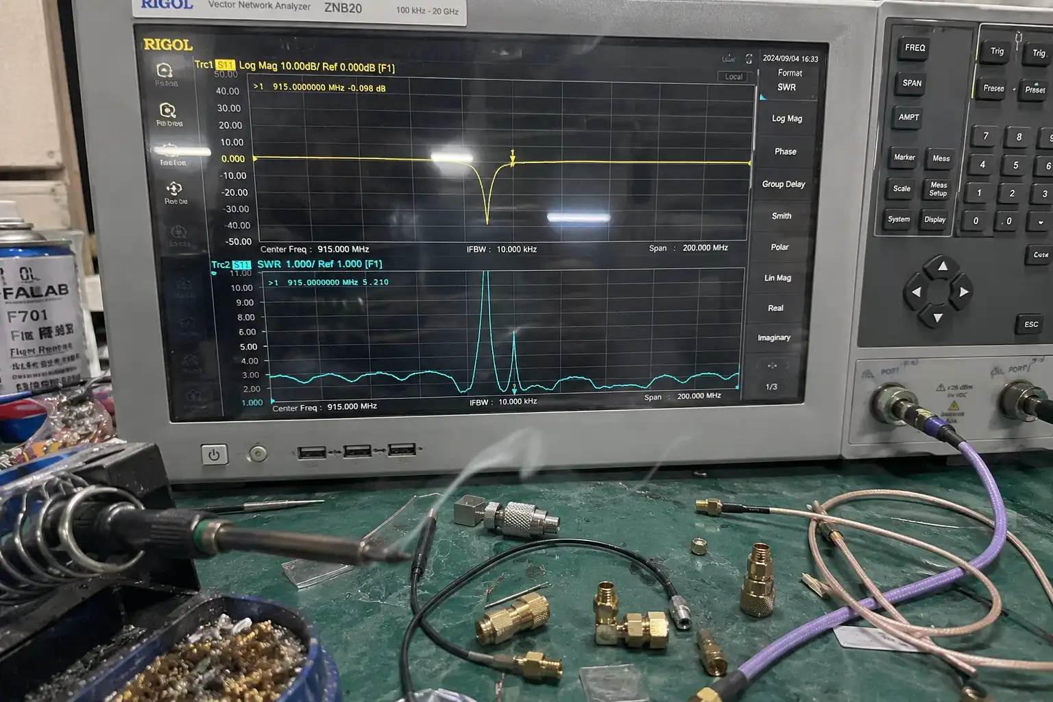
Network analyzer S11 trace at a hand-soldered DIY RF switch junction showing severe return loss and VSWR drift from the 50-ohm target

Insertion loss is the power you pay at every connector, every via, every unsoldered ground return. In the DIY switch the postmortem team built, the cascade of electromechanical relays and hand-soldered SMA junctions produced attenuation that compounded port to port. The network analyzer trace told the story without ambiguity: severe S11 return loss attenuation at the custom switch junctions, meaning energy meant for the antenna was being reflected back into the reader instead of radiated into the field above the tokens.

VSWR degradation follows directly from that mismatch. A reader designed for a 50-ohm load sees a boundary it did not anticipate, and the standing-wave ratio climbs. As VSWR degrades, forward power drops while reflected power rises; the tag field weakens exactly where you need it strongest — directly above a dense stack of tokens. The baseband decode window then fills with corrupted packet preambles because the backscatter return is too weak and too noisy to lock onto a clean transition.

The engineering trade-off between cascading external switches and deploying a native multiport module is not close:

Dimension DIY External RF Switch Cascading Integrated Multi-Port Native Reader Modules
RF Path Loss Additive insertion loss at every relay and SMA junction (3–6 dB cumulative) Single matched TX path per port; under 1 dB typical
VSWR Drifts to 2:1 or higher under cascade mismatch Held near 1.2:1 by on-module matching network
S11 Return Loss Severe attenuation at hand-soldered junctions (postmortem-confirmed) Spec-controlled, verified at factory calibration
Port Sync No shared clock; handoff gaps corrupt preambles Single synthesizer; phase-aligned TDM handoff
Scalability Hard ceiling at two to three ports before lockups Four to eight ports native; expandable via daisy-chain
Phase Coherence None across ports; random relative phase Maintained by shared local oscillator across all ports
Cost of Ownership Low BOM, high field-failure and rework cost Higher capex, near-zero RF rework

The GS1 EPC Gen2 air-interface specification defines the tag's backscatter timing budget down to the microsecond; when your forward link is degraded by switch insertion loss, you violate that budget at the physical layer before the protocol state machine ever engages (GS1 EPC Gen2 UHF air interface). The reader cannot negotiate around a weakened carrier — the tag simply never reaches its activation threshold.

For verified insertion-loss and VSWR figures per port, the Fongwah Official Product Catalog & Datasheets provides calibrated S-parameter summaries you can drop directly into a link-budget model without trusting a hand-built fixture. The temptation to cascade a switch is understandable on a spreadsheet. In the field it is a deferred failure: the insertion loss and VSWR degradation do not announce themselves, they accumulate until the read rate crosses the threshold your automation cell can no longer tolerate. By then the missed reads have already propagated into downstream inventory and billing errors.

Why Circular Polarization is Mandatory for Randomized Tag Orientations

Key Takeaway: Linear-polarized fields read only tags aligned to the polarization axis, so randomized token orientations produce blind spots that no amount of TX power can repair. The micro-hardware root cause is polarization mismatch between a fixed linear axis and the arbitrary orientation of thin stacked tags.

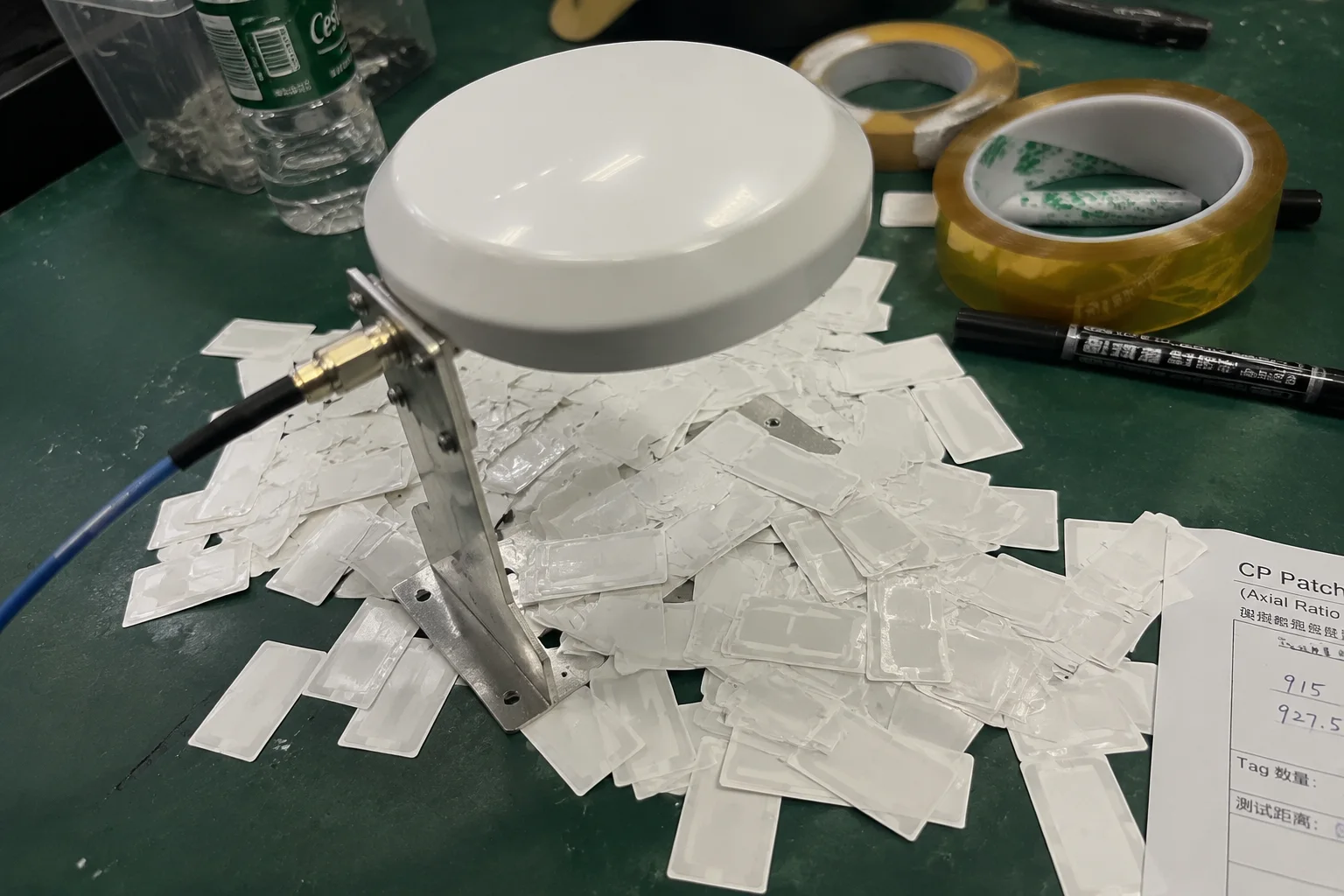
Circular-polarized RFID field covering token tags dropped at randomized angles where a fixed linear antenna leaves blind spots

A token dropped onto a tabletop does not care about your antenna's polarization axis. It lands at 37 degrees, or face-down on a neighbor, or edge-on against a rail. A linear-polarized antenna radiates a field aligned to one axis; a tag whose dipole is orthogonal to that axis receives almost no energy and backscatters almost nothing. In a randomized population this is not an edge case — it is the majority case, and raising TX power only deepens the standing wave, it does not fix the geometry.

Circular polarization resolves the orientation problem. A right-hand or left-hand circularly polarized field carries energy in every rotational plane, so a tag at any orientation couples to at least one component of the rotating field. For dense tabletop token tracking where operators do not orient tags by hand, circular polarization is not optional — it is a hard requirement for a defensible first-pass read rate.

The cost is a roughly 3 dB theoretical link-budget penalty versus a perfectly aligned linear pair, but that penalty is recovered many times over by eliminating polarization-blind misses. The postmortem cell initially used linear panels; switching to circular-polarized patch antennas over each zone removed an entire class of "missing tag" reports that had been misattributed to the DIY switch. Once the field geometry was fixed, the remaining failures traced cleanly to the RF path loss the switch was introducing — the two failure modes had been masking each other in the telemetry.

Thin token tags stacked near each other also depolarize the return through mutual interaction, which further argues for circular polarization with a defined circular polarization axis. When metal-backed tokens are in play, the reflected field can invert handedness; selecting the correct CP sense per zone — and sometimes alternating RHCP and LHCP between adjacent zones to suppress cross-talk — is part of the layout engineering, not an afterthought. Leading reader vendors document this exact trade-off in their antenna application notes for dense near-field environments, and the recommendation is consistent: specify CP wherever tag presentation is untended.

Solving Mutual Inductive Detuning in Densely Stacked Tag Populations

Key Takeaway: Densely stacked thin tags couple inductively and pull each other off the ETSI 865–868 MHz resonance, so the population detunes as a group rather than as individuals. The micro-hardware root cause is mutual inductive coupling plus close-overlap tag shielding that drives RSSI below the receiver sensitivity threshold.

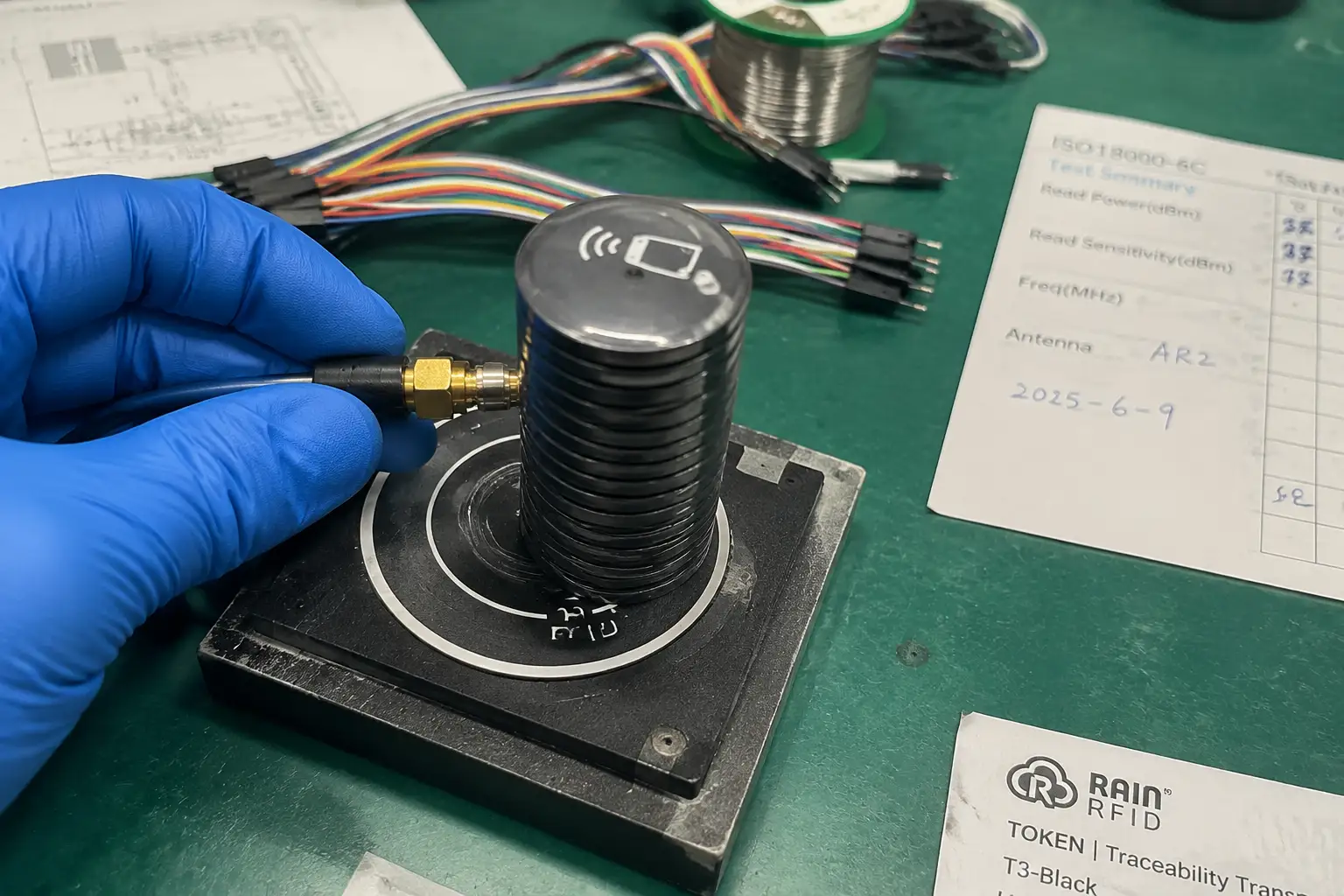
Cross-section of densely stacked thin RFID token tags showing mutual inductive coupling and top-tag shielding that suppresses lower-tag RSSI

Stack a dozen thin token tags within inches of each other and you no longer have twelve independent resonators — you have one coupled network. Mutual inductive coupling shifts each tag's effective resonant frequency away from the standard ETSI 865–868 MHz band. The postmortem network analysis showed clusters of tags detuning together, which is precisely why misses appeared in batches rather than as isolated single-tag dropouts.

Operating inside the regulated RFID frequency regulations by country band is non-negotiable; the ETSI EN 302 208 standard defines the 865–868 MHz envelope for European deployments together with the power spectral density and out-of-band emission limits you must stay within (ETSI EN 302 208). When mutual coupling detunes tags outside that window, you lose them legally and physically at the same moment — the reader can no longer energize them and the regulator would not permit you to chase them anyway.

Mitigation is both mechanical and electrical. Increasing inter-tag spacing beyond the coupling radius, inserting ferrite or RF absorber between layers, and reducing stack density all lower the mutual inductance that drives the detuning. On the reader side, frequency-agile tuning that sweeps the interrogator across the band can re-acquire detuned tags, and per-port RF tuning trims the match to the loaded environment rather than to an empty test fixture.

Close tag overlap also produces shielding: the top tag shadows the ones beneath it, and RSSI for the lower tags drops below the receiver sensitivity threshold. The diagnostic telemetry confirmed this directly — RSSI values for shielded tags fell under the sensitivity floor while the top tag in the same stack read cleanly. The fix combines spatial de-stacking with higher-gain circular-polarized antennas and a native multiport reader that can raise per-port TX power without destabilizing VSWR.

This is where the corrected topology from the earlier sections pays off. Native multiport modules hold VSWR near 1.2:1 even at elevated TX power, so you can push field strength down into the stack without the reflection penalty the DIY switch imposed. You recover the shielded tags without trading away the regulatory margin — a combination a cascaded-switch design cannot deliver.

Pre-Order Verification FAQs

Q: Our procurement spec allows cascaded external switches to protect capex — why mandate native multi-port modules?

A: Because the capex you save on the switch is spent many times over in insertion loss, VSWR degradation, and field rework. The postmortem quantified 3–6 dB cumulative RF path loss across the DIY cascade and severe S11 return loss at every hand-soldered junction; that attenuation directly caused the ~20% read miss the automation cell could not tolerate. Native multiport modules eliminate the second impedance boundary entirely — each port is a matched 50-ohm TX path calibrated at the factory, with a shared synthesizer maintaining phase coherence during TDM handoff. For a four-zone tabletop cell the total cost of ownership favors native modules once you price the engineering hours lost to lockups and the inventory errors those lockups cause downstream. The external switch is not a cheaper path; it is a deferred failure with a date stamped on it.

Q: How do you guarantee phase coherence across ports during TDM polling?

A: Phase coherence is a function of a single local oscillator distributed to every port, which only exists when the ports share one RF synthesizer on one module. In the cascaded-switch topology there is no shared clock, so relative phase across ports is random and the baseband preamble capture is unstable from one dwell to the next. Native multiport readers derive all port carriers from one phase-locked LO, so each TDM dwell window opens with a known, repeatable phase relationship to the previous one. We validate this at incoming inspection with a vector network analyzer measuring S21 phase stability port to port across the full TDM cycle, and we supply the resulting S-parameter report with every module shipment so your integration team can model the link budget directly instead of trusting a datasheet headline number.

Conclusion

The postmortem is unambiguous: a single-channel reader behind a DIY RF switch cannot track densely stacked token tags across four close-coupled zones. The losses are physical — insertion loss, VSWR degradation, mutual inductive detuning, and polarization blind spots — not firmware bugs you can patch. The engineering answer is a native multiport UHF architecture with circular polarization, shared-synthesizer phase coherence, and a calibrated 50-ohm match at every port.

Contact Fongwah Technology through our Initiate Direct Factory RFQ Portal Evaluation to begin a technical review.

Related Technical Articles

FACTORY DIRECT

Ready to Discuss Your Custom RFID Project Requirements?

Connect directly with our manufacturing experts for technical hardware architecture validation, encryption review, and bulk OEM pricing.

Corporate RFQ Desk

B2B Evaluation Response within 24 hours

20+
Years OEM
6
Prod Lines
100%
QC Tested

Start Your RFQ

Connect directly with our engineering team.

🛡️ 100% Secure & confidential. NDA available upon request.

Chat with us