
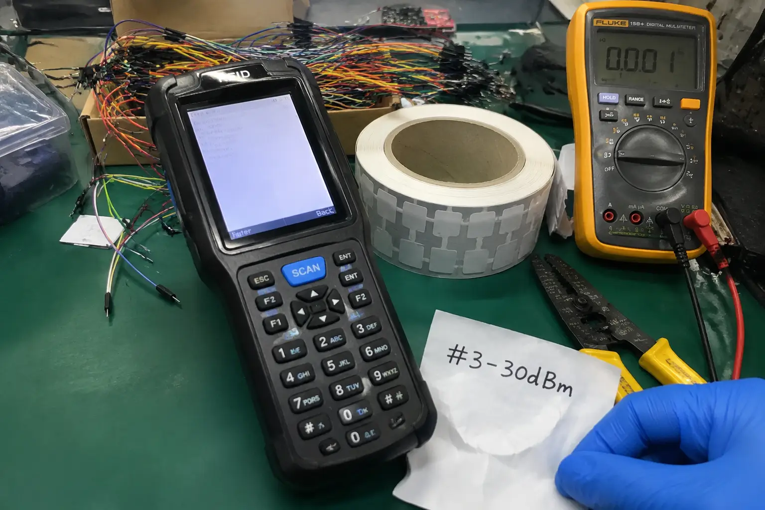
truggling with RFID data corruption during inventory setup? Your handheld reader is likely overwriting adjacent tags, causing chaos. Understanding the physics of RF bleed-through is the only way to fix it.
Handheld readers fail at high-density encoding because their unshielded RF field is too broad. It accidentally powers and writes to multiple small, clustered tags at once. This effect, called parasitic coupling1, corrupts data and makes accurate inventory commissioning impossible with a handheld device.
If you're new to the technology, start with what RAIN RFID is — the UHF standard governed by the RAIN RFID Alliance.
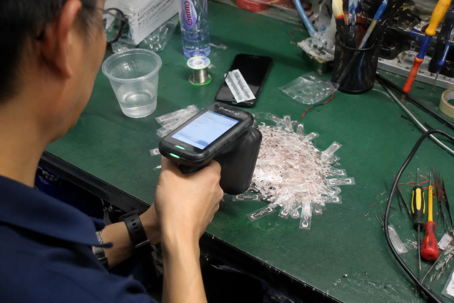
I was recently called in to perform a postmortem on a major retail deployment failure — a textbook example of why RFID deployments fail at data initialization. The client was trying to provision over a thousand UHF RFID jewelry tags for a new inventory system. They were using a standard handheld terminal to encode each tag one by one on a workstation. The result was a complete disaster. We found widespread database SKU mismatches and corrupted Electronic Product Code (EPC) payloads. The project was dead on arrival, not because of faulty tags or software, but because of a fundamental misunderstanding of RF physics. Let's break down exactly what went wrong so you can avoid it.
What is the Hidden Trap of Handheld Multi-Tag Encoding in Retail Inventory?
The handheld's RF field is not a precise beam; it's a wide cone of energy2 that bleeds into the surrounding area. This RF bleed-through energizes and communicates with any tag within its range, not just the single tag you are aiming at, leading to accidental writes.
You think you are efficiently encoding tags one by one. In reality, you are silently creating a database nightmare. The trap is assuming your reader is only talking to the tag directly in its sights.
The hidden danger of using a handheld for bulk encoding is assuming the RF field is a precise, laser-like beam. It's not. It's a broad cone of energy that wakes up and communicates with any tag that meets its power threshold. This means tags adjacent to, or even underneath, your target tag can also receive the write command.
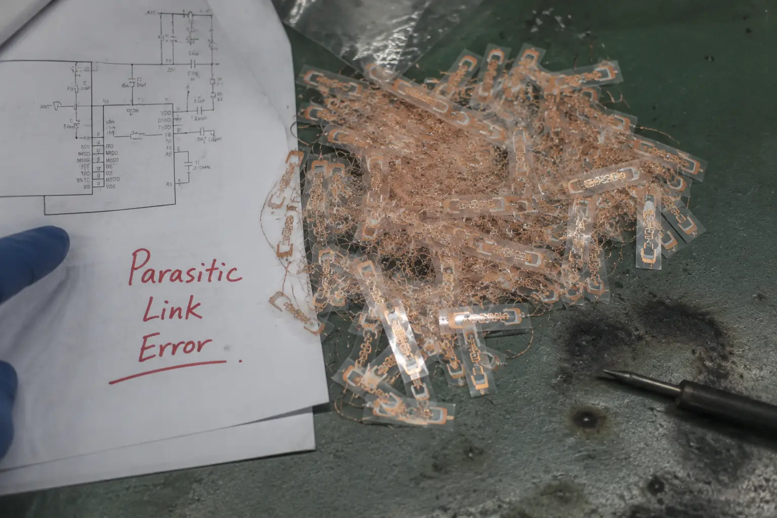
In the retail failure I analyzed, the operator was placing dozens of small optical flag tags on a desk for commissioning. They would point the handheld reader at one tag, send the write command, and move to the next. What they couldn't see was the RF energy "spilling" over and energizing two or three other tags simultaneously.
The reader's anti-collision algorithm, which is designed to read many tags quickly, could not prevent a powerful write command from being partially or fully accepted by multiple tags at once.3 This resulted in a chain reaction of data corruption. The inventory database became unreliable before a single item even hit the sales floor, a catastrophic failure rooted entirely in using the wrong hardware architecture for the job.
How Does Near-Field Parasitic Coupling Cause Adjacent Tag Overwrites?
The handheld's RF energy doesn't just target one tag; it bleeds into a 3D radius. This "parasitic coupling" gives enough power to adjacent tags to wake them up and accept write commands intended for another tag.
You are pointing the reader at one tag. But the tag right next to it is the one getting written to, or both are. This isn't a glitch; it's the predictable result of near-field physics.
When small tags are clustered together, the handheld reader's RF output couples with multiple antennas parasitically. These nearby tags absorb enough wake-up power ($P_{th}$) to enter the reply state4. This causes severe air-interface collisions5 and allows them to receive and process write commands not meant for them.
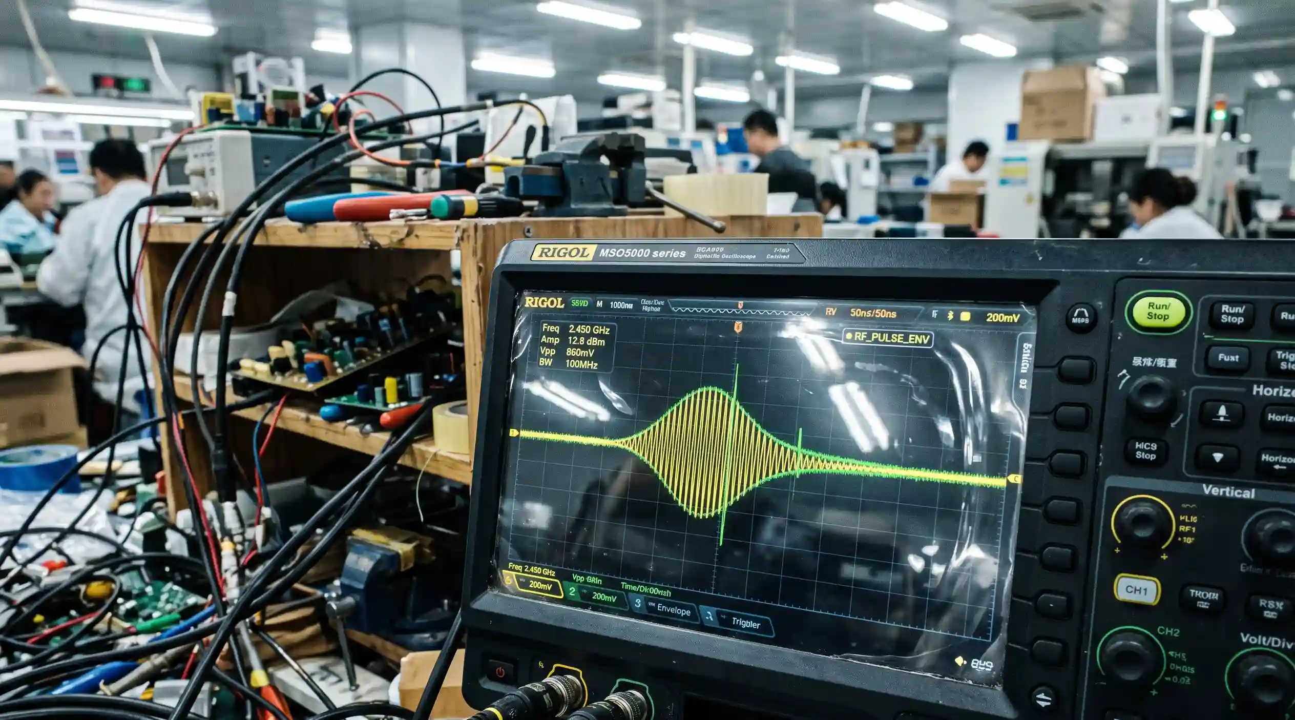
During the postmortem, our diagnostic telemetry told the whole story. We saw trailing byte corruption across sequential write operations in the data logs. An RSSI (Received Signal Strength Indicator) threshold analysis revealed that adjacent tags were absorbing sufficient power to activate and respond. This is the core of parasitic coupling.
The RF energy from the reader antenna creates a field that links with the antenna of the target tag. But in a high-density setup, that same field also links with other tag antennas nearby. These "parasite" tags wake up and listen. When the write command is issued, the reader has no definitive way to ensure only one tag accepts it. The problem is made worse by the very small form factor of jewelry and optical tags, which are often piled in dense clusters on the encoding desk, creating a perfect storm for RF collisions.
Field behavior is also shaped by regional power limits — review RFID frequency regulations by country before you design or tune any encoding field. For antenna-level guidance on shrinking the stray field footprint, see Impinj's <a href="https://support.impinj.com/hc/en-us/articles/202756888-Monza-X-Antenna-Design-Application-Note" rel="nofollow">Monza-X antenna design application note</a>.
Symptom Diagnosis: How to Recognize Parasitic-Coupling Encoding Failures
Parasitic coupling leaves four repeatable signatures in your commissioning data. Learning to read them separates a genuine RF architecture fault from ordinary operator error — and tells you when training will never be enough.
You ran the batch, the software reported "success," and yet your inventory database looks wrong. Before you blame the operator, check for these four signatures of adjacent-tag overwrite. Each one appears in real postmortems, and together they point to a single root cause.
1. Cross-Item SKU Contamination
The most visible signal is a tag carrying the EPC of a completely unrelated product. If a jewelry tag suddenly reports the EPC of an eyewear SKU placed three slots away, an adjacent tag absorbed your write command. This is the clearest, most undeniable fingerprint of parasitic coupling — the tag physically next to your target was the one that got written.
2. Trailing-Byte Corruption
The write reports "success," but EPC playback shows dropped or scrambled trailing bytes. This happens when a competing tag interrupts the write mid-stream, so the target tag commits only a partial payload. Trailing-byte corruption is the classic fingerprint of a contested write — two tags fighting over one command.
3. Intermittent, Unreproducible Failures
Under identical settings, Tag A encodes cleanly while Tag B fails for no obvious reason. Metal reflections, tag stacking, and antenna orientation create unpredictable hot spots across the desk. When failures are random and cannot be reproduced on demand, the cause is the RF environment itself, not the person holding the reader.
4. Database Reconciliation Drift
Your physical cycle count and your system quantity slowly diverge over time, even though "every tag encoded successfully." Silent overwrites accumulate as phantom SKUs and missing items. Drift is the long-tail cost of unverified adjacent writes, and it shows up weeks after commissioning, long after the operator has moved on.
If two or more of these signatures appear, you are facing an architecture problem, not a process problem. No amount of operator training can patch an RF gap that physically exists in an unshielded field.
Why Do Shielded Encoding Zones Matter for Small Form-Factor Optical Tags?
A shielded encoding zone, like an RFID printer or a dedicated chamber, creates a controlled "Faraday cage" environment6. It physically blocks RF signals from reaching any tag except the single one being encoded, eliminating all risk of parasitic coupling.
You are still dealing with tag overwrites. Your inventory is a mess, and you're blaming the tags or the software. The issue is the uncontrolled RF environment, and the only solution is to control it physically.
Shielded encoding zones are non-negotiable for high-accuracy bulk encoding. They physically isolate the target tag from all RF interference. By creating an RF-blocking enclosure, they prevent the reader's energy from bleeding onto adjacent tags. This guarantees that only the intended tag's integrated circuit is powered and written to.
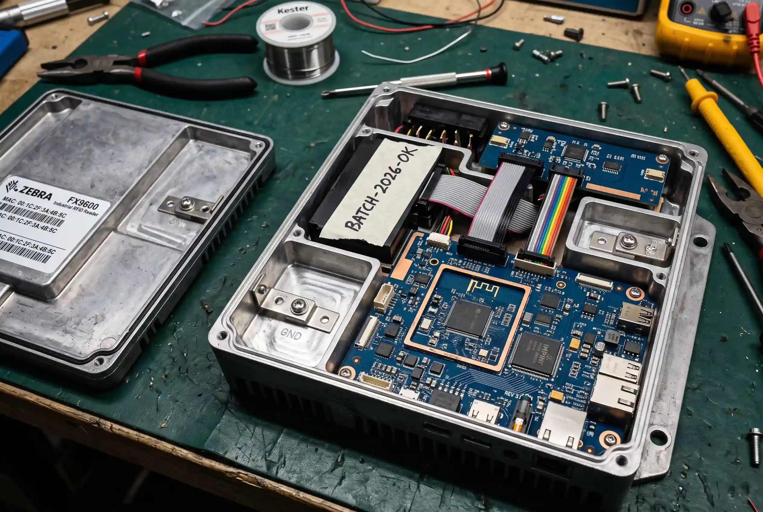
The difference between a handheld reader and a shielded encoding station is the difference between shouting in a crowded room and having a private conversation. The shielded environment creates a small, localized, and predictable RF field. Only the tag passing directly through this zone is activated. All other tags outside the shield remain inert.
This is the only way to guarantee the 1-to-1 relationship between a write command and a tag needed for commissioning. This principle is why dedicated RFID printers and encoding stations exist. They solve the physics problem that handhelds cannot. The hardware inside these systems, often sourced directly from the Fongwah Embedded RFID Reader Module Catalog, is specifically engineered for this controlled application.
Handheld vs. Shielded Encoding Architecture Comparison
| Feature | Handheld Serial Multi-Tag Write | Shielded Printer Encoding Architecture | RFID Printer (Inline) |
|---|---|---|---|
| RF Field Control | Uncontrolled, wide broadcast cone | Tightly controlled, physically contained field | Fully enclosed, focused field |
| Adjacent Tag Isolation | None; high risk of parasitic coupling | Complete; RF shielding blocks stray energy | Complete; RF shielding blocks stray energy |
| Write Accuracy | Low and unpredictable | Extremely high; near 100% accuracy | Extremely high; near 100% accuracy |
| Data Verification | Unreliable; may verify the wrong tag | Reliable; performs write-then-verify on isolated tag | Reliable; performs write-then-verify on isolated tag |
| Susceptibility to Tag Density | Very high; performance degrades with density | None; immune to tag density outside the zone | None; immune to tag density outside the zone |
| Best Use Case | Mobile inventory audits (reading) | Stationary bulk commissioning (writing) | High-volume inline encoding |
How Do You Choose the Right Hardware Architecture for Interrogator-to-Tag Link Verification?
The right architecture prioritizes a confirmed write-then-verify sequence7 within a physically isolated RF environment. This means using fixed or embedded readers with shielded antennas or dedicated RFID printers, not general-purpose handhelds for bulk provisioning.
You know you need better hardware now. But choosing the wrong "upgrade" can lead to the same failures. The key is to select an architecture that guarantees the write-verify link is secure and isolated.
To ensure data integrity, you must choose hardware that performs a closed-loop, write-then-verify process inside a shielded zone. An embedded reader module integrated into a custom encoding station or a dedicated RFID printer is the correct architecture. This setup confirms the correct EPC is written before the tag ever leaves the isolated zone.
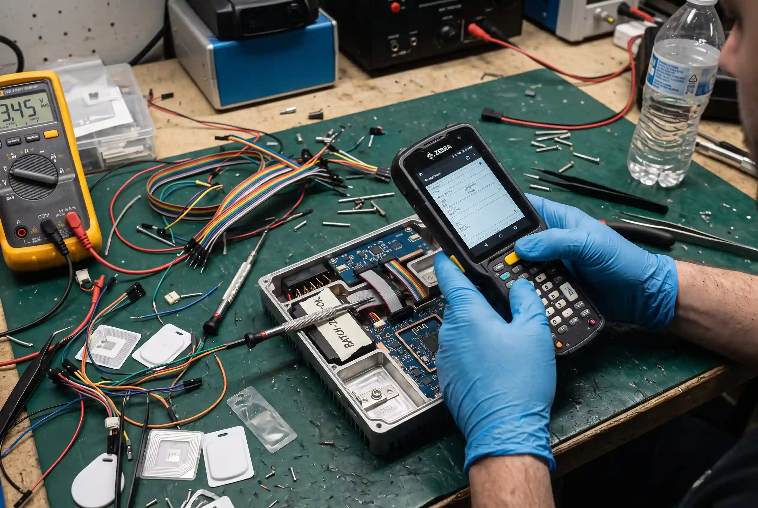
The interrogator-to-tag link is the two-way communication path where the reader sends commands and the tag responds. For encoding, verification is critical. But verification is useless if you are not 100% certain you are verifying the tag you just tried to write. A handheld in an open environment cannot provide this certainty. A shielded station can.
By using purpose-built hardware, like the fixed readers and modules available in the FONGWAH RFID Smart Card & Tag Series, you build a system where the process is deterministic:
- A single tag enters the shielded zone.
- The reader encodes the EPC data.
- The reader immediately reads the tag to verify the data was written correctly.
- The tag exits the zone.
This workflow is impossible with a handheld reader in a high-density environment. The solution is not a "better" handheld. It is a fundamental shift in strategy from mobile convenience to stationary accuracy for the critical task of inventory commissioning. For help selecting the right architecture, see our RFID reader buying guide.
Understanding where RFID rollouts break during data initialization helps you design the link-verification stage before it becomes a field failure. In apparel retail, the same principle underpins RAIN RFID retail loss-prevention programs — source tagging at a shielded station prevents the downstream EPC corruption that triggers false shrinkage alerts. The write-then-verify loop itself follows the <a href="https://ref.gs1.org/standards/gen2/" rel="nofollow">GS1 EPC Gen2 standard</a>, which defines the command and response sequences a compliant tag must honor.
Pre-Order Verification FAQs (Technical Support & Integration)
- Answer: This is a common misconception that confuses reading with writing. While reducing power and using RSSI filters can help clean up noise during a read audit, they are unreliable and dangerous for writing. In a dense cluster of small tags, RSSI is not a good indicator of distance8. A tag that is physically closer but poorly oriented can have a weaker signal than a farther tag with a perfect orientation9 to the reader's antenna. If you lower the power too much, you risk failed writes on your actual target tag because there is insufficient power to flip the non-volatile memory bits10. If you rely on RSSI filtering, you are just guessing. Software cannot solve a near-field physics problem. Physical RF isolation is the only deterministic method to guarantee that your write command energizes one and only one tag IC.
Q2: We need mobility. A fixed station is too restrictive for our process. Isn't there a better handheld solution for this specific problem?
-
Answer: This objection comes from trying to use one tool for two very different deployment operations: commissioning and auditing.
- Commissioning (Encoding): This is a one-time, high-stakes process where 100% data integrity is required. It is best performed in a controlled, stationary environment before items are put into inventory. The proper workflow should be: Bulk encode tags at a shielded station, verify each payload, and then apply them to products.
- Auditing (Cycle Counting): This is a continuous process where mobility is key. Handheld readers are the perfect tool for quickly scanning tagged items on shelves or in a stockroom after they have been accurately commissioned.
There is no handheld reader designed to reliably perform high-density bulk encoding without violating basic principles of electromagnetic propagation. The right solution is to use the right tool for each stage of the life cycle: a stationary shielded station for encoding, and a mobile handheld for auditing.
Q3: Our handheld vendor claims their "proximity mode" handles this. Why invest in another piece of hardware?
- Answer: "Proximity mode" is usually a software power reduction, not a physical field change. It lowers transmit power, but the reader's radiation pattern stays just as wide. In a dense stack, reflected energy and adjacent tags still receive enough power to accept a write. A shielded encoder solves this differently: it physically contains the field inside a Faraday cage, so only the tag inside the zone is ever energized. The result is repeatable and deterministic, whereas proximity mode only makes the failure less frequent. If your commissioning accuracy depends on a settings toggle, you haven't solved the physics — you've merely masked it.
- Answer: Yes, significantly. Small tags pack more antenna area into a smaller physical footprint, which raises the mutual inductance between neighbors. When you stack or cluster them tightly — as happens with jewelry and optical tags on a commissioning desk — the coupling strength increases and the overwrite risk multiplies. This is exactly why dense, small-form-factor tag populations need a shielded zone most. The physical isolation of a shielded encoder neutralizes the mutual inductance that a handheld inevitably excites.
Q5: Is a write-then-verify loop really necessary, or is a simple pass/fail enough?
- Answer: For low-value, low-volume encoding, a binary pass/fail check may be acceptable. But in a retail rollout, a single corrupted EPC poisons every downstream system that reads it — the cost of one bad tag spreads across the whole chain. A proper write-then-verify loop uses RSSI and phase telemetry to catch "weak success" tags that a pass/fail check would miss. The verification step costs almost nothing at line speed, while a corrupted database costs far more to clean up later. For commissioning, the verify step is not optional.
Conclusion
For high-density bulk encoding of small tags, handheld readers are the wrong tool for the job. You must use stationary, shielded hardware to physically isolate each tag, preventing parasitic coupling and data corruption.
Contact Fongwah Technology through our Initiate Direct Factory RFQ Portal Evaluation to begin a technical review.
"Near-Field Communication in Biomedical Applications - PMC - NIH", https://pmc.ncbi.nlm.nih.gov/articles/PMC7864326/. ↩
"Design of spiral-shaped UHF near-field reader antenna for RFID ...", https://ieeexplore.ieee.org/document/6027212/. ↩
"[PDF] EPC Radio-Frequency Identity Protocols Generation-2 UHF RFID", https://www.gs1.org/sites/default/files/docs/epc/Gen2_Protocol_Standard.pdf. ↩
"[PDF] High Sensitivity Near-zero Power Wakeup Receiver for ...", https://par.nsf.gov/servlets/purl/10350399. ↩
"[PDF] EPC Radio-Frequency Identity Protocols Generation-2 UHF RFID", https://www.gs1.org/sites/default/files/docs/epc/Gen2_Protocol_Standard.pdf. ↩
"Faraday cage - Wikipedia", https://en.wikipedia.org/wiki/Faraday_cage. ↩
"Guidelines for securing Radio Frequency Identification ( ...", https://www.govinfo.gov/content/pkg/GOVPUB-C13-8506922fd706b620b3373caefb73e9f5/pdf/GOVPUB-C13-8506922fd706b620b3373caefb73e9f5.pdf. ↩
"[PDF] Is RSSI a Reliable Parameter in Sensor Localization Algorithms", https://cse.buffalo.edu/srds2009/F2DA/f2da09_RSSI_Parameswaran.pdf. ↩
"Tag-Array-Based UHF Passive RFID Tag Attitude ... - PMC - NIH", https://pmc.ncbi.nlm.nih.gov/articles/PMC11478726/. ↩
"EEPROM - Wikipedia", https://en.wikipedia.org/wiki/EEPROM. ↩