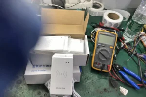
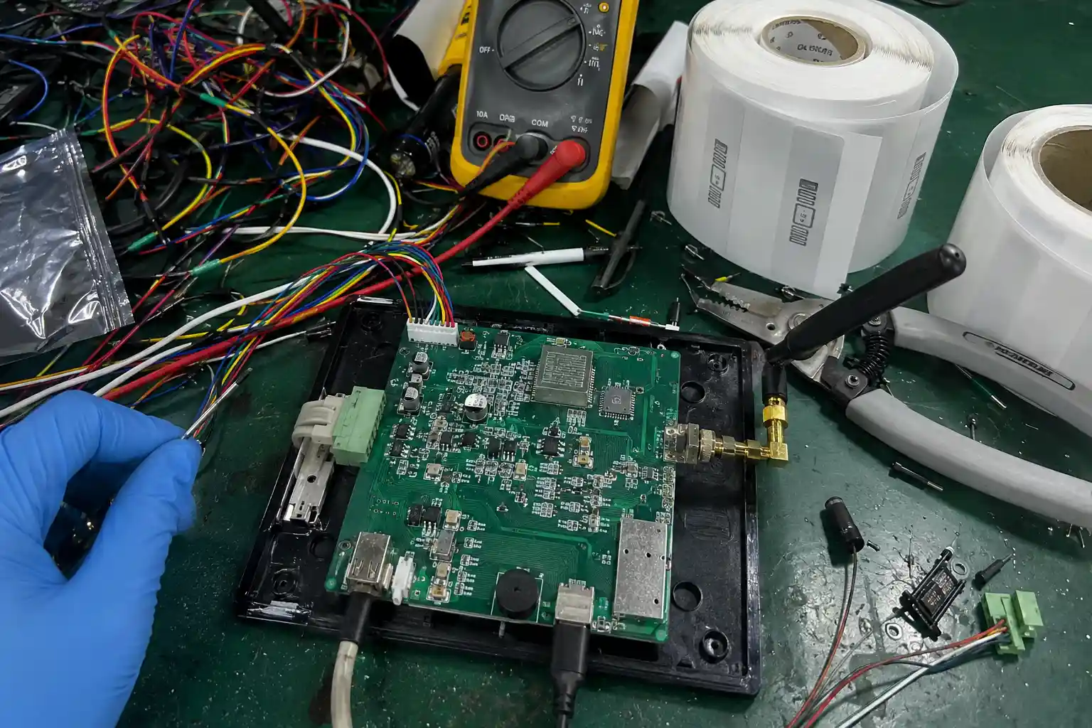
Struggling with RFID readers that work initially but then mysteriously fail? These system lockups halt operations, and the root cause is often hidden within the hardware's micro-environment, not the software.
The most common reasons RFID reader modules fail during continuous polling are poor hardware design and environmental interference.1 Factors like inadequate PCB shielding, unstable power delivery, stray capacitance from metallic enclosures, and thermal-induced component drift corrupt data signals, leading to UART lockups and complete communication loss.
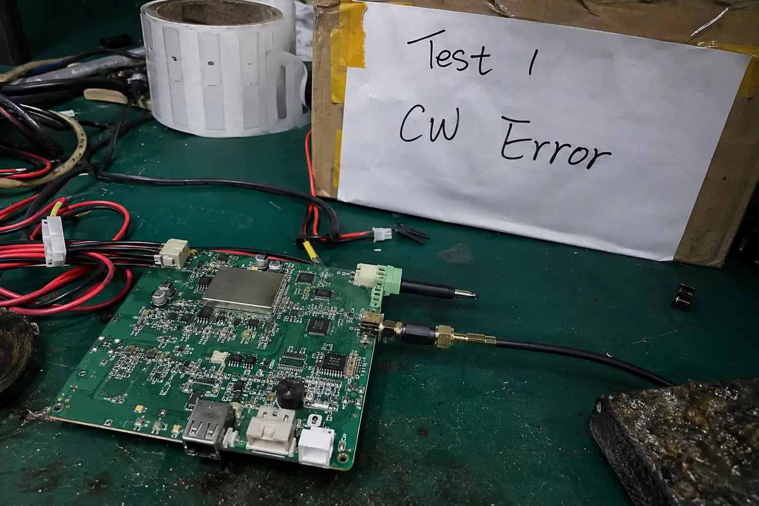
I’ve seen this exact failure mode cripple high-throughput systems firsthand, from automated logistics hubs to secure pharmaceutical vaults. The pattern is always the same: initial success followed by catastrophic, seemingly random drops. The good news is these failures aren't random at all. They are predictable outcomes of specific hardware vulnerabilities. Let’s break down the engineering reality behind why these communication links collapse under pressure, and more importantly, how to build systems that don't.
How does poor PCB shielding cause RFID reader instability?
Your embedded reader performs perfectly on a clean workbench, but inside its final metal chassis, it becomes unreliable. You blame the firmware, but the real culprit is often the unshielded circuit board.
Poor PCB shielding allows ambient electromagnetic interference (EMI) from motors, power lines, or even digital clocks to inductively couple onto sensitive RF and data traces. This injected noise corrupts the signal integrity, causing bit errors that lead to communication instability and system lockups2.
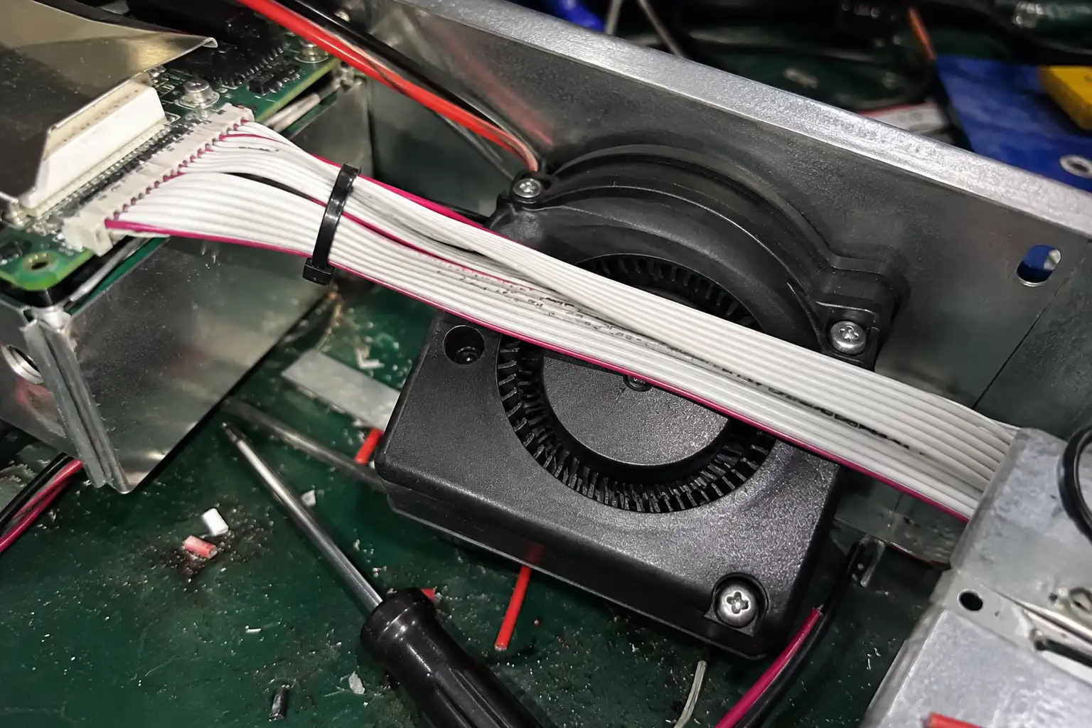
In one of my recent failure analyses, the client’s module was placed inside a compact, metallic drug validation vault. This enclosure, while necessary for security, created a hostile RF environment. The module’s unshielded flat ribbon cables for UART communication were routed directly alongside the wiring for a DC blower fan. Every time the fan spooled up, its motor generated a significant electromagnetic field. This field induced a noisy, fluctuating current in the parallel data lines—a classic case of inductive coupling.3 The result was a corrupted data stream that the microcontroller couldn't decode, leading to a total interface lockup. A properly engineered module, like those in the Fongwah Embedded RFID Reader Module Catalog, mitigates this with integral shielding and robust ground plane design, isolating sensitive RF sections from noisy digital components and external interference sources.
Engineering Comparison: Shielding Impact
| Metric | Unshielded Module Behavior | Properly Mitigated Architecture |
|---|---|---|
| Signal-to-Noise Ratio (SNR) | Degrades significantly near EMI sources | Maintained due to integral shielding |
| Bit Error Rate (BER) | High, causing packet loss/corruption | Near zero, ensuring data integrity |
| System Stability | Prone to lockups under load | Consistent, reliable operation |
| Ground Plane | Susceptible to ground loops and noise | Isolated RF/Digital grounds prevent noise |
What triggers UART serial lockups during high-frequency pharmacy validation sweeps?
Your automated pharmacy system halts during peak hours, creating critical delays. The issue isn't transaction volume; it's the hardware's inability to handle the continuous polling required for high-frequency validation.
UART lockups are triggered by a degraded signal-to-noise ratio on the data lines, often caused by unfiltered power supply ripple.4 During intense, continuous polling, this noise floor rises, corrupting start/stop bits and causing framing errors that ultimately freeze the serial port controller.
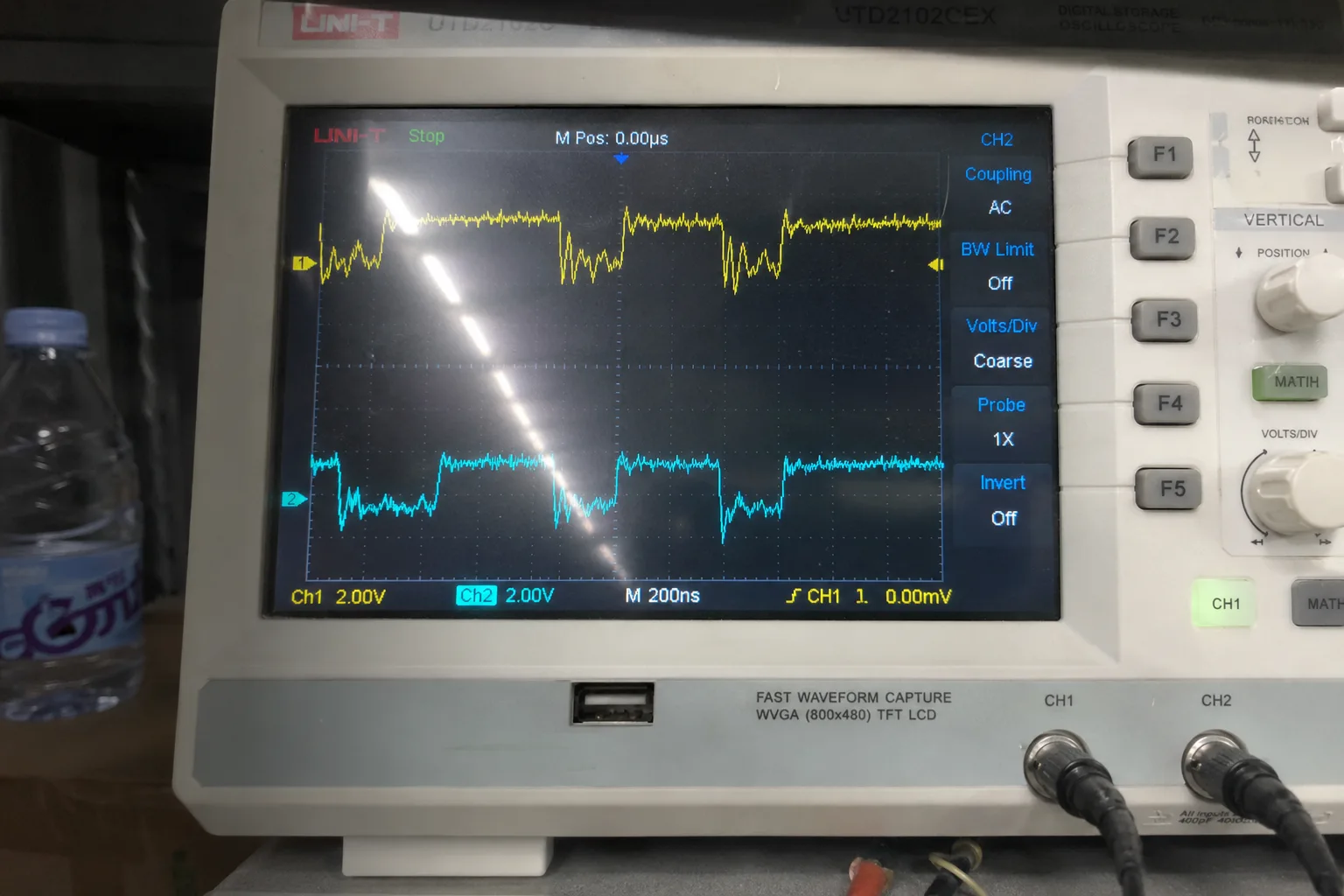
The automated pharmacy vault I investigated used a shared 5V power rail for the RFID module, the master controller, and several small motors. Scoping the power line revealed severe, unfiltered voltage ripple that coincided perfectly with motor activation. This noise directly translated onto the UART TX/RX lines. While the system could handle a few corrupted bytes during sparse polling, the continuous, high-frequency sweeps demanded by the validation process were fatal. The constant stream of noisy data led to repeated framing errors. The UART receiver's buffer would overflow with garbage data, and eventually, the controller would enter a locked state, requiring a hard reset. This highlights the absolute necessity of a clean power source, managed by on-board Low-Dropout Regulators (LDOs) with a high Power Supply Rejection Ratio (PSRR). You can review specs for modules designed to handle these conditions in the Fongwah Official Product Catalog & Datasheets.
Deeper Dive: Power and Data Corruption
- Power Rail Noise: Unfiltered switching power supplies and shared power rails with motors introduce high-frequency noise and voltage droop.
- Signal Integrity Violation: This noise couples into the digital logic, shrinking the valid voltage margin for a logical HIGH or LOW.
- Baseband Decoding Failure: The UART receiver samples the line at specific intervals to read bits. If noise causes the voltage to be in an indeterminate state during a sample, it reads the wrong value.
- Framing Errors & Lockup: A single incorrect stop bit can cause a framing error. A continuous stream of these errors during intense polling overwhelms the controller's error handling, leading to a full bus lockup.5
How do stray capacitance and parallel DC fan noise impact HF modules?
Your HF reader works flawlessly in open air but suffers a dramatic range reduction once installed in its metal housing. The culprit is not a faulty antenna, but parasitic effects from the enclosure itself.
A nearby metallic chassis creates stray capacitance with the module's antenna trace, detuning its 50-ohm impedance matching network. This mismatch increases VSWR, reflects power, and kills read range.6 Simultaneously, noise from parallel DC fans couples onto data lines, corrupting communication.
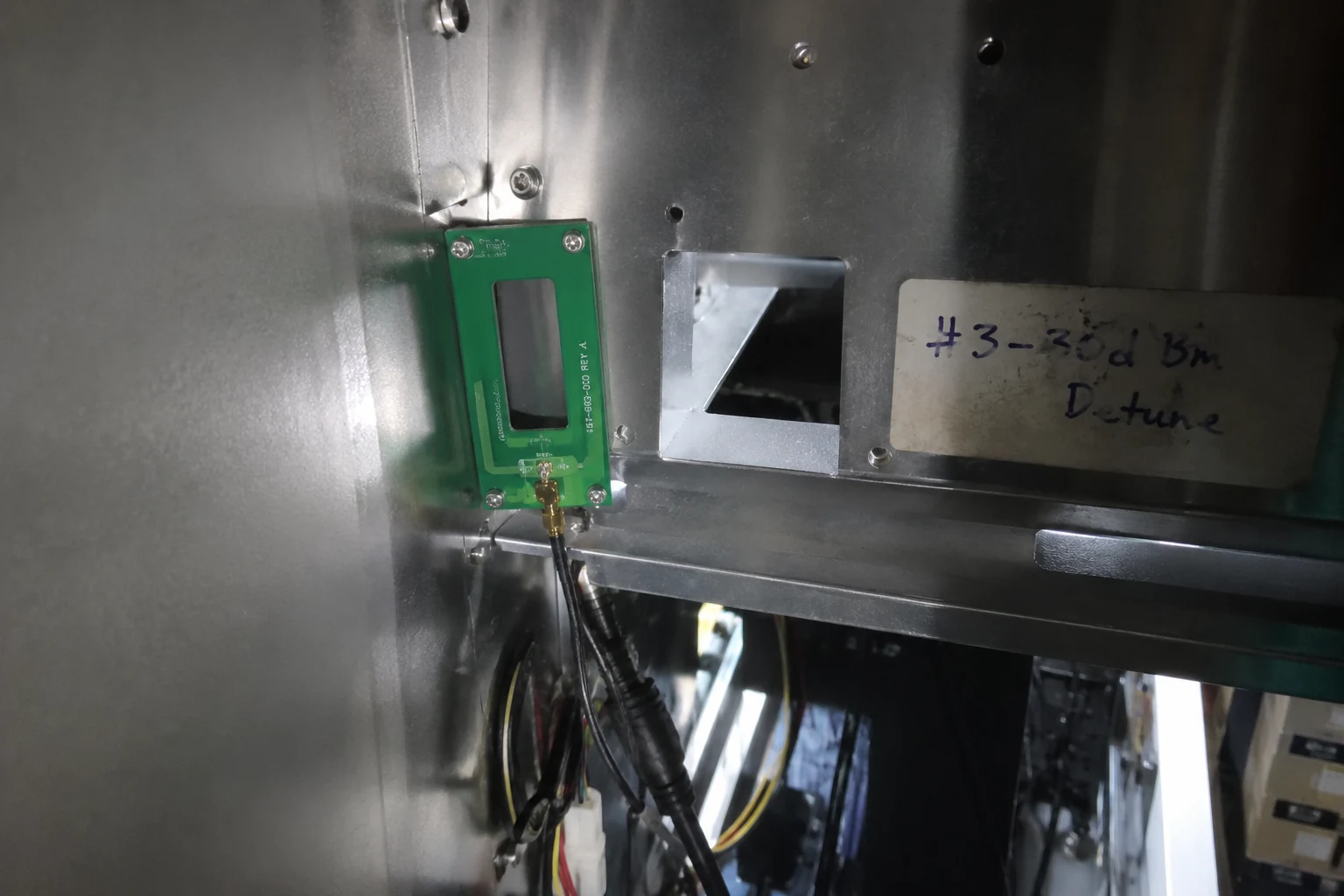
Every RF engineer learns early on that the environment is part of the circuit. When you place an HF module (operating at 13.56 MHz) close to a metal wall, you essentially create a new, unwanted capacitor between the antenna trace and the metal ground plane. This parasitic capacitance throws the entire antenna matching network out of balance. Instead of a perfect 50-ohm load, the power amplifier now sees a mismatched impedance. This causes a high Voltage Standing Wave Ratio (VSWR), where a significant portion of the RF energy is reflected back into the amplifier instead of being radiated by the antenna. This not only cripples read performance but can also damage the amplifier over time. Add the constant electromagnetic buzz from a nearby DC fan, and you have a recipe for total system failure. This is why our design process, detailed in the Fongwah Industrial RFID Knowledge Base, emphasizes robust layout practices that account for these real-world integration challenges.
How do you diagnose floating TTL logic states and oscillator thermal drift under continuous wave load?
Your system experiences random data corruption, and debugging the software yields no answers. The problem is likely at the physical layer, where voltages are not behaving as they should and components are overheating.
Use an oscilloscope to probe the UART data lines. Floating TTL logic states—voltages hovering illegally between 0.8V and 2.0V—cause unpredictable behavior.7 They are a clear sign of noise or grounding issues. Simultaneously, monitor the carrier frequency; drift indicates the crystal oscillator is overheating8.
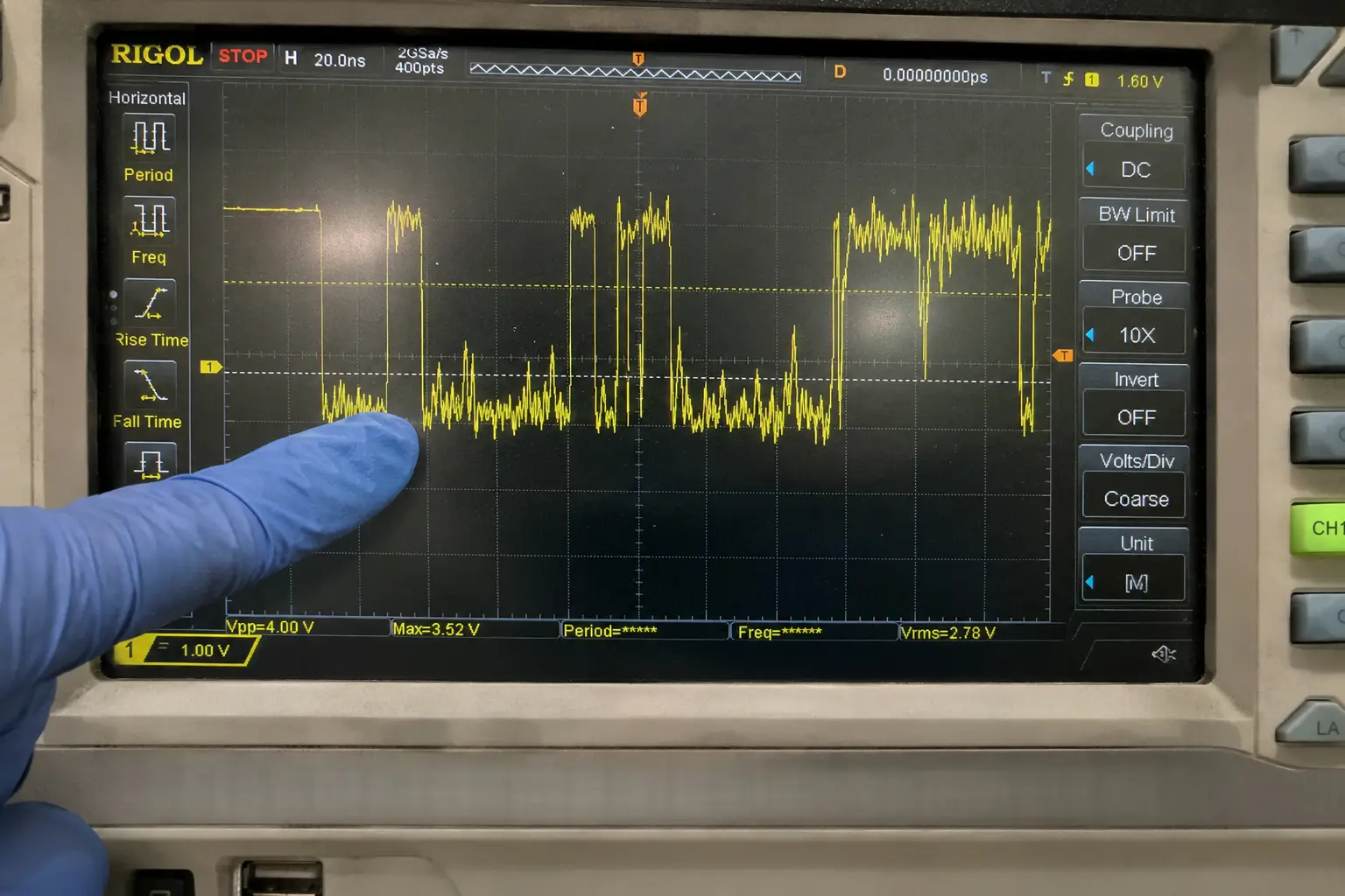
In the pharmacy vault failure, probing the UART lines was the "aha" moment. We saw the logic level hovering in the forbidden zone between the valid threshold for a logic LOW (V_IL < 0.8V) and a logic HIGH (V_IH > 2.0V). This floating state meant the receiving chip couldn't decide if the bit was a '0' or a '1', leading to random data. This was caused by the combination of power rail noise and poor grounding. Furthermore, leaving the reader in a continuous wave (CW) transmit state for several minutes generated significant heat. A spectrum analyzer showed the 13.56 MHz carrier frequency drifting by several kilohertz. This thermal drift of the main crystal oscillator is catastrophic because all system timing, including the window for decoding tag responses, depends on a stable clock.9 Modules without robust thermal management and Schmitt trigger inputs, which provide hysteresis to clean up noisy signals10, are destined to fail in continuous-operation environments.
Engineering Comparison: Thermal & Logic Stability
| Parameter | Standard Module Under CW Load | Thermally-Managed Module |
|---|---|---|
| Local Oscillator (XO) | Drifts outside of tolerance due to heat | Stable frequency via TCXO or good heatsinking |
| Logic Levels | Float into indeterminate zones with noise | Clean HIGH/LOW states via Schmitt triggers |
| Decoding Window | Shrinks and shifts, causing read errors | Remains stable for reliable demodulation |
| Long-Term Reliability | High risk of thermal failure or data loss | Designed and tested for 24/7 operation |
Pre-Order Verification FAQs
Q1: Your modules look robust, but our deployment environment is extremely noisy with lots of metal and motors. How do you guarantee stability against EMI and detuning where other readers have failed?
A1: We guarantee stability through a multi-faceted design architecture. First, our modules are built on multi-layer PCBs with dedicated internal ground planes that shield sensitive RF traces. Second, we use integral shielding cans over the RF front-end and microcontroller to block external EMI. Third, our power architecture uses high-PSRR LDOs to filter out noise from the host system's supply rail. Finally, every data and control input is buffered through a Schmitt trigger, which provides significant hysteresis to reject noise and prevent floating logic states. Each design is validated against a battery of tests, including direct EMI injection and operation within resonant metallic cavities, to ensure performance meets datasheet specifications in worst-case scenarios, not just on a clean bench.
Q2: We need to run continuous 24/7 polling cycles for inventory tracking. How do your modules handle the thermal load without performance degradation or frequency drift?
A2: We address thermal stability at both the component and system levels. We specify high-grade, temperature-compensated crystal oscillators (TCXOs) for critical applications, which maintain frequency stability across a wide operating temperature range11. The layout of the PCB includes large copper thermal pads connected to the ground plane, effectively using the entire board as a heatsink to draw heat away from the power amplifier and processor. Our power amplifiers are selected for high efficiency to minimize waste heat generation from the start. Most importantly, every module undergoes a full-load, multi-hour burn-in aging test to verify that its carrier frequency remains within the tight tolerance required for reliable tag communication, even under sustained CW load.
Conclusion
RFID reader failures are rarely due to a single cause. They stem from a cascade of hardware-level issues: EMI, power instability, parasitic effects, and thermal drift, all conspiring to corrupt data.
Contact Fongwah Technology through our Initiate Direct Factory RFQ Portal Evaluation to begin a technical review.
"Radio Frequency Identification (RFID) technology and patient safety", https://pmc.ncbi.nlm.nih.gov/articles/PMC3872592/. Research on RFID system reliability confirms that hardware-level issues, including component selection, PCB design, and environmental factors like electromagnetic interference, are significant contributors to reader malfunction and performance degradation. Evidence role: general_support; source type: research. Supports: That hardware design flaws and environmental conditions are primary causes of RFID reader failures.. ↩
"[PDF] Exploring the Performance and Reliability of Communication Links ...", https://stacks.cdc.gov/view/cdc/215747/cdc_215747_DS1.pdf. Engineering principles of signal integrity dictate that external noise, such as electromagnetic interference (EMI), can reduce the noise margin of a digital signal, increasing the probability of bit errors. An accumulation of these errors can lead to protocol failures and system lockups. Evidence role: mechanism; source type: education. Supports: That electromagnetic interference degrades signal integrity, which increases the bit error rate and can cause system instability.. ↩
"Electromagnetic interference - Wikipedia", https://en.wikipedia.org/wiki/Electromagnetic_interference. Inductive coupling is a form of electromagnetic interference where the time-varying magnetic field from a source conductor (e.g., motor wiring) induces a current in a nearby victim conductor (e.g., a data line), thereby corrupting the intended signal. Evidence role: definition; source type: encyclopedia. Supports: The definition and mechanism of inductive coupling as a form of electromagnetic interference.. ↩
"Power Supply Noise - an overview | ScienceDirect Topics", https://www.sciencedirect.com/topics/computer-science/power-supply-noise. Application notes and research on mixed-signal circuit design show that insufficient Power Supply Rejection Ratio (PSRR) can allow noise from the power supply (ripple) to couple onto digital communication lines, degrading the signal-to-noise ratio and leading to errors such as framing errors in UART communication. Evidence role: mechanism; source type: paper. Supports: That noise from a power supply can couple into data lines, degrading the signal and causing communication errors.. ↩
"Getting a frame error in UART - Arm-based microcontrollers forum", https://e2e.ti.com/support/microcontrollers/arm-based-microcontrollers-group/arm-based-microcontrollers/f/arm-based-microcontrollers-forum/547855/getting-a-frame-error-in-uart. In many microcontroller peripherals, a continuous stream of data with framing or parity errors can fill error-status registers and trigger repeated interrupts. If not handled correctly by the firmware, this can lead to a state machine lockup within the peripheral, requiring a hardware reset to resolve. Evidence role: mechanism; source type: education. Supports: That persistent data corruption can lead to communication interface lockups in microcontrollers.. ↩
"Standing wave ratio - Wikipedia", https://en.wikipedia.org/wiki/Standing_wave_ratio. Voltage Standing Wave Ratio (VSWR) is a measure of impedance mismatch in an RF system. A high VSWR signifies that a large portion of the transmitted power is reflected back towards the source instead of being radiated by the antenna, leading to a significant reduction in effective communication range. Evidence role: mechanism; source type: education. Supports: The relationship between impedance mismatch, VSWR, and effective radiated power.. ↩
"Transistor–transistor logic - Wikipedia", https://en.wikipedia.org/wiki/Transistor%E2%80%93transistor_logic. Standard 5V Transistor-Transistor Logic (TTL) defines a logic LOW as a voltage below 0.8V (V_IL) and a logic HIGH as a voltage above 2.0V (V_IH). Any voltage between these two thresholds falls into an indeterminate region where the logic gate's output is not guaranteed, leading to unpredictable circuit behavior. Evidence role: definition; source type: institution. Supports: The standard voltage levels for TTL logic and the concept of the indeterminate region.. Scope note: While these values are classic for 5V TTL, modern logic families (e.g., 3.3V CMOS) use different voltage levels, but the principle of an indeterminate region between valid logic states remains fundamental. ↩
"Frequency drift - Wikipedia", https://en.wikipedia.org/wiki/Frequency_drift. The resonant frequency of a quartz crystal is temperature-dependent, typically following a parabolic curve. Significant temperature changes, such as those from component overheating, will cause the oscillator's output frequency to drift away from its nominal value, a phenomenon known as thermal drift. Evidence role: mechanism; source type: research. Supports: That temperature changes, including overheating, cause frequency drift in crystal oscillators.. ↩
"[PDF] How Accurate is a Radio Controlled Clock?", https://tf.nist.gov/general/pdf/2429.pdf. In digital communication systems, a stable clock is essential for synchronous data sampling and decoding. In RF systems like RFID, the carrier frequency and the timing for demodulating backscattered signals from a tag are derived from this clock; significant drift can make decoding impossible. Evidence role: general_support; source type: education. Supports: That a stable clock source is critical for the timing of digital communication and RF systems.. ↩
"[PDF] Application Brief - Understanding Schmitt Triggers - Texas Instruments", https://www.ti.com/lit/scea046. A Schmitt trigger is a comparator circuit that uses positive feedback to create two distinct switching thresholds for rising and falling signals. This gap between thresholds, known as hysteresis, prevents unwanted oscillations and provides immunity to noise on the input signal. Evidence role: definition; source type: encyclopedia. Supports: The function of a Schmitt trigger and its use of hysteresis to reject noise.. ↩
"Crystal oscillator - Wikipedia", https://en.wikipedia.org/wiki/Crystal_oscillator. A Temperature-Compensated Crystal Oscillator (TCXO) is an advanced oscillator that incorporates a temperature-sensing network to generate a correction voltage, which is applied to a variable-capacitance diode in the crystal circuit. This actively counteracts the crystal's natural frequency drift with temperature, resulting in significantly higher stability over a wide operating range compared to a standard oscillator (XO). Evidence role: definition; source type: education. Supports: The definition and purpose of a Temperature-Compensated Crystal Oscillator (TCXO).. ↩