
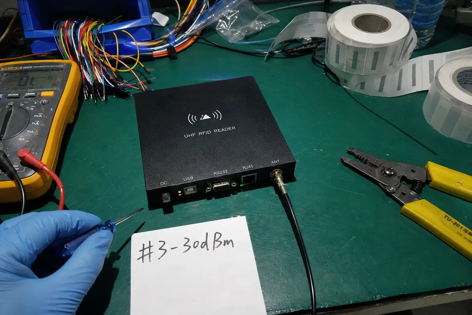
High-duty-cycle card issuance centers frequently encounter sudden device dropouts and transaction freezes during continuous encryption runs. This issue directly causes industrial throughput instability and latency propagation across corporate credentialing pipelines. The physical root cause is thermal runaway localized within the desktop reader's radio frequency (RF) stage due to fundamental board-level design omissions1.
The most common reason cheap desktop RFID readers freeze is unmanaged thermal runaway. Low-cost hardware design omits dedicated aluminum heat sinks and printed circuit board (PCB) thermal via arrays. Under continuous card encoding runs, the RF Power Amplifier (PA) rapidly clips past structural thermal limits, inducing master clock cycle dropouts, SPI bus timing degradation, and cryptographic authentication timeout codes.
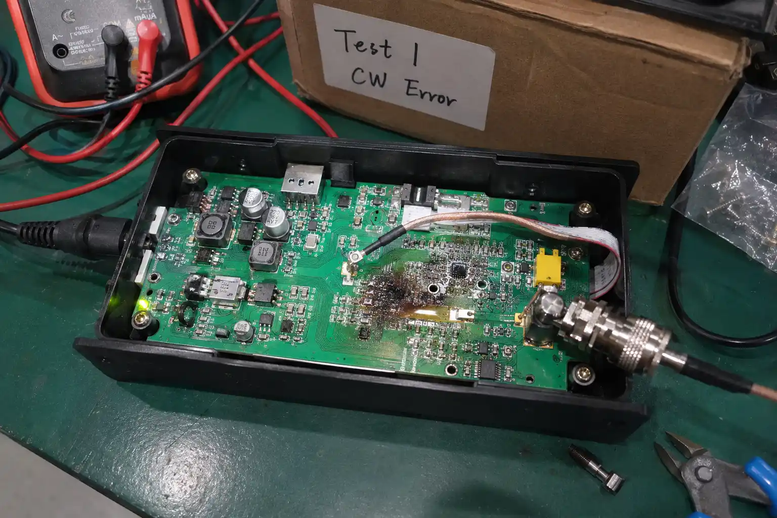
Field postmortems of low-cost desktop deployments consistently reveal a specific failure envelope. A reader functions within stable parameters for the initial 20 to 30 card verification cycles2. However, as duty cycles extend, the host software hangs, the device status register stops responding, and the unit requires a hard power cycle via USB disconnection to restore baseline operational capacity. This behavior stems entirely from hardware architecture failures rather than firmware source errors. Below is a micro-level engineering breakdown of how these thermal bottlenecks cascade into total data link failure.
What Causes Sudden Device Freezes During High-Volume Card Issuance?
Under high-volume batch issuance conditions, an RFID desktop reader operates at near-continuous load, maintaining an active, energized electromagnetic carrier field for extended execution windows. On low-cost hardware platforms, this operational stress triggers a swift descent into thermal runaway.
Device freezes during high-volume card encoding are caused by thermal saturation of the RF front-end. Continuous wave transmission forces the power amplifier into high thermal dissipation states3. Lacking an efficient dissipation path, the localized junction temperature reaches critical structural limits, degrading the electrical properties of neighboring digital logic and locking up the microprocessor.
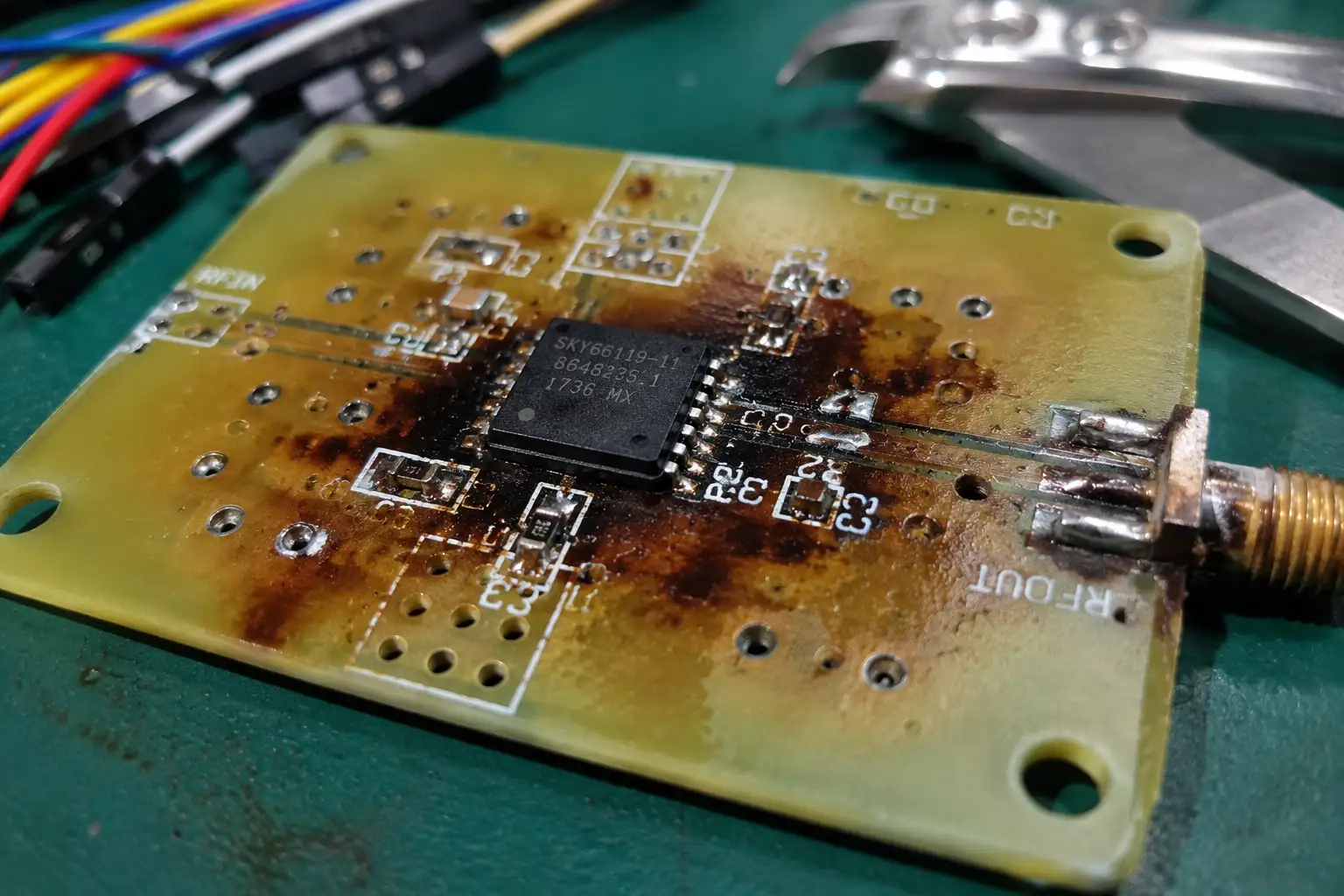
Continuous Wave Power Saturation
To initialize cryptographic sector handshakes with contactless smart cards, the reader’s power amplifier (PA) must emit sustained continuous wave (CW) RF output power. This high-duty-cycle process converts a significant percentage of incoming electrical current into localized thermal energy as a operational byproduct. In precision-engineered B2B hardware, this thermal accumulation is pulled away through dedicated ground planes. In cheap desktop alternatives, this heat stays trapped on the surface layers of the board, accelerating thermal breakdown.
Oscillator Frequency Drift and SPI Instability
Every digital RFID architecture relies on a master crystal oscillator to provide precise clock synchronization for baseband processing. When the reader's inner casing reaches thermal saturation, this intense heat propagates into the adjacent clock generation circuits.
The heat induces severe frequency drift in the crystal oscillator4. Once the master clock begins dropping cycles or jittering, timing margins on synchronous communication protocols—specifically the SPI (Serial Peripheral Interface) bus between the RF transceiver and the microcontroller—completely break down5. The baseband processor can no longer interpret register commands, forcing the reader into a hard freeze state.
What Are the Hidden Hardware Flaws in Cheap RFID Readers?
Teardowns of low-cost readers reveal clear architectural shortcuts aimed at passing basic laboratory bench tests while ignoring long-term continuous field deployment requirements.
Cheap desktop readers reduce manufacturing costs by omitting physical thermal management components. They completely strip away dedicated aluminum or copper heat-sink plates from the active RF elements6. Furthermore, their multi-layer PCBs omit thermal via stitching arrays under the PA's thermal pad, effectively blocking the heat from reaching internal copper layers.
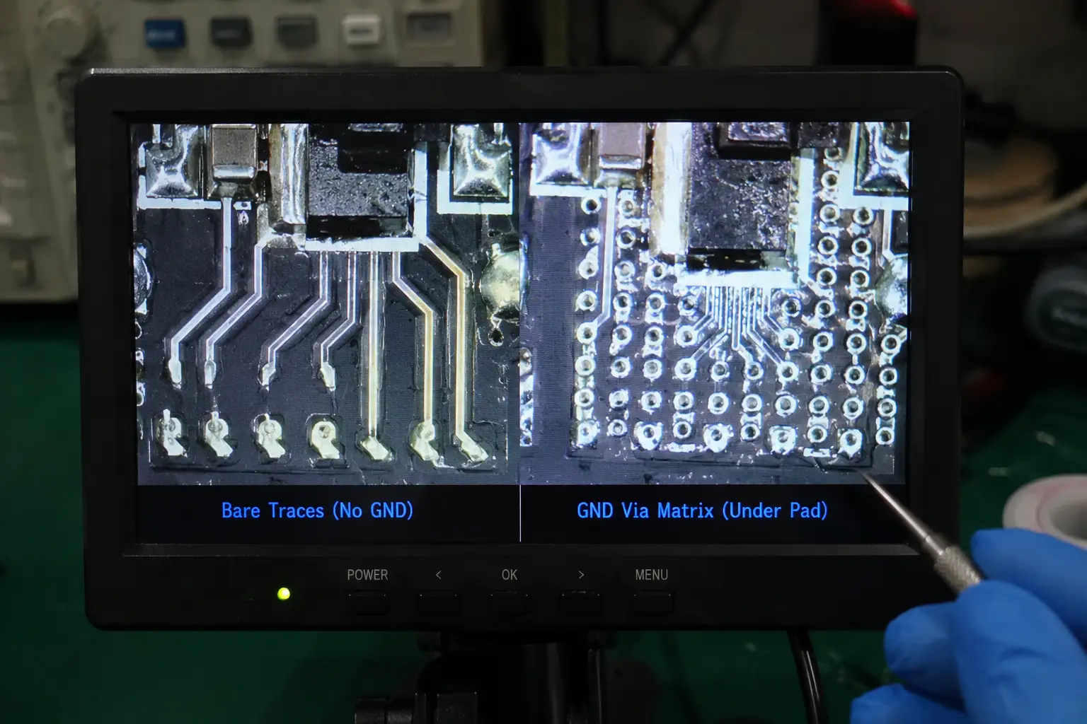
The Absence of Via Stitching and Heat-Sinking
In professional hardware design, a heat sink provides the expanded physical surface area necessary to radiate convective heat away into the surrounding air structure. Complementing this, thermal vias—small plated holes drilled beneath high-heat silicon components—act as low-resistance thermal conduits7. They channel heat away from the delicate top trace layer directly into the thick internal copper ground planes, which function as an integrated thermal sink.
| Thermal Engineering Feature | Low-Cost Reader Design | FONGWAH Industrial-Grade Design |
|---|---|---|
| Active Component Cooling | None; relies entirely on stagnant air within plastic casing | Custom-milled internal aluminum heat-sink array |
| PCB Thermal Pathways | Missing thermal vias; heat is fully trapped on surface traces | Dense thermal via stitching directly to heavy internal ground planes |
| Impedance Behavior | Rapid impedance shift; component thermal clipping | 50-ohm stable matching network across full load profiles8 |
| System Outcome | Hardware lockups and crypto timeout codes within 30 mins | 24/7 continuous wave stability under full batch issuance |
Without these micro-hardware implementations, the thermal energy generated by continuous wave transmissions is trapped inside the small plastic enclosure. The localized junction temperatures climb rapidly, altering the transistor characteristics within the PA and causing immediate thermal clipping.
How Does Severe Thermal Clipping Trigger MIFARE Crypto Validation Timeout Errors?
One of the most complex symptoms of an overheating desktop reader is the sudden appearance of random communication failures during secure sector initialization on MIFARE cards, returning standard cryptographic timeout exceptions.
Thermal clipping shifts the electrical impedance of the RF stage out of optimal 50-ohm boundaries, driving a severe Voltage Standing Wave Ratio (VSWR) mismatch. This mismatch degrades the modulation depth of the backscattered signal, disrupting the microsecond timing required for secure MIFARE challenges and responses. This mismatch closes the reader's data-demodulation window, triggering a validation timeout code.
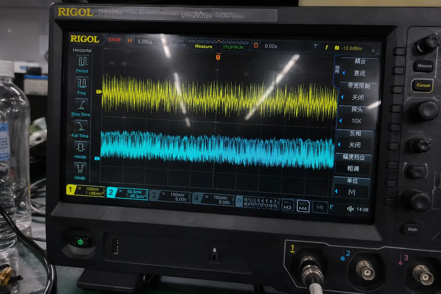
The MIFARE Cryptographic Handshake Constraint9
Accessing secure sectors on a MIFARE card requires a precise, multi-step cryptographic handshake. The communication protocol demands that both the reader and the card exchange tokens within strict, microsecond-level timing frames. If the response from either node exhibits jitter or arrives outside the programmed time-slice window, the authentication sequence aborts instantly, and the host system registers a "crypto validation timeout."
VSWR Disruption and Phase Noise Expansion
As thermal clipping degrades the internal transistors of the power amplifier, the output impedance of the RF stage shifts dramatically away from its calibrated 50-ohm target. This severe impedance mismatch triggers high reflected energy back into the system, degrading the VSWR boundary.
Concurrently, thermal stress expands phase noise across the carrier wave10. The reader’s receiver stage can no longer accurately isolate and decode the subtle subcarrier modulation returned by the smart card. Timing frames drift out of synchronization, data packets warp, and the system experiences a total validation failure—frequently resulting in interrupted card data writes or corrupted sector trailer keys.
Technical Reliability Validation & Thermal Mitigation
B2B system integrators and software developers require hardware assets that maintain zero-dropout performance boundaries under continuous load. To completely eliminate thermal runaway risks, specific hardware isolation boundaries must be applied directly at the component-level layout stage across all high-performance product branches.
An industrial-grade architecture utilizes a multi-layered, active thermal dissipation system. The board layout links a custom-milled internal aluminum heat sink directly to the core RF stage, supported by extensive multi-layer thermal via stitching arrays. Furthermore, proprietary firmware incorporates automated standby logic that ramps down active continuous wave output power during idle intervals to minimize base heat generation.
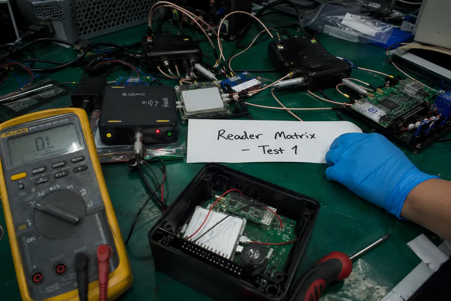
Every device engineered for professional deployment assumes rigorous, continuous execution environments. This requires addressing heat dissipation directly during early board-level architecture routing, specifically for specialized desktop systems. You can evaluate these hardware deployment parameters across our dedicated Fongwah RFID Reader and Module Line.
Core Hardware Mitigations
Our industrial-grade thermal management framework balances three essential engineering strategies:
- Precision PCB Ground Pours: We route extensive thermal via stitching directly beneath the RF power amplifier, anchoring the thermal pad to a heavy internal copper ground plane to turn the entire multi-layer board into an efficient thermal distributor.
- Dedicated Heavy Aluminum Sinks: We couple the PA package directly to a custom-fitted aluminum heat-sink block, ensuring rapid convective dissipation away from sensitive digital crystal oscillators.
- Automated Standby Protocol Arrays: Our firmware dynamically monitors transmission lines. The reader drops out of continuous wave power execution when it detects no active token presence, cutting idle thermal generation during intense encoding runs.
This focus on robust hardware integrity is standard across our complete production pipeline. You can review our full design validations in the FONGWAH RFID Smart Card & Tag Series and access deep-dive deployment analysis through our Fongwah Industrial RFID Knowledge Base. The result is a desktop architecture that maintains verified, rock-solid timing windows, stable VSWR matching, and zero cryptographic timeout errors over 24/7 deployment timelines.
Pre-Order Verification FAQs (Technical Support & Integration)
Q1: If we replace our failing low-cost readers with the Fongwah industrial desktop line, will our existing software stack require a complete API/SDK rewrite?
- Answer: No. Fongwah desktop reader-writers utilize highly encapsulated, backward-compatible firmware architectures. We deliver comprehensive cross-platform wrapper blocks across C#, Java, Python, and C++ that directly map into your existing standard baseband command execution layers. If you are communicating via standard native Windows/Linux wrappers or virtual COM interfaces, our underlying memory sector authentication and MIFARE handshake protocol routines sync seamlessly with your established calling logic, eliminating the need to re-architect your high-level transaction pipelines.
Q2: How does the Fongwah reader ensure reliable 50-ohm impedance matching and prevent antenna polarization mismatch when deployed on standard, metallic workstation surfaces?
- Answer: Hardware enclosure separation physics alone cannot fully insulate an RF stage from inductive surface loading. Fongwah addresses localized workstation metal detuning directly through board-level impedance engineering. Our industrial desktop platforms implement a rigid secondary capacitive-inductive vector matching network coupled with automated VSWR boundary clipping firmware. Even when placed directly on a continuous steel table or near a heavy access lock chassis, the reader dynamically stabilizes its return loss boundaries within tight limits, suppressing phase noise expansion and preventing modulation depth collapse inside the backscatter receiving window.
Conclusion
Low-cost desktop RFID readers cut costs by omitting core thermal management components, ensuring device failures during intense card issuance cycles. High-duty-cycle enterprise card encoding requires robust hardware designs built around proven thermal via stitching and dedicated heat-sinking arrays.
Contact Fongwah Technology through our Initiate Direct Factory RFQ Portal Evaluation to begin a technical review.
"Thermal runaway in large format semi-solid-state cells: Analysis of ...", https://www.sciencedirect.com/science/article/pii/S2352152X26015148. Electronics reliability literature documents thermal runaway in RF power amplifiers as a consequence of insufficient heat dissipation paths at the board level, including absent ground-plane coupling and missing thermal vias (see, e.g., IPC-2152 thermal management standards or equivalent peer-reviewed failure analysis studies). Evidence role: mechanism; source type: paper. Supports: The mechanism by which inadequate PCB thermal design causes localized thermal runaway in RF power amplifier stages. Scope note: General RF amplifier thermal runaway literature may not address the specific low-cost RFID reader form factor described in the article. ↩
"Effects of different anisotropically conductive adhesives on the ...", https://www.sciencedirect.com/science/article/abs/pii/S0143749615001657. Empirical reliability studies on RFID reader hardware under sustained duty cycles would contextualize the claimed 20–30 cycle failure threshold; absent such a citation, the figure remains an unverified field estimate. Evidence role: statistic; source type: paper. Supports: The approximate number of continuous read/write cycles before thermal-induced failure occurs in low-cost RFID hardware. Scope note: Published benchmarks may use different duty-cycle definitions or hardware categories, making direct comparison to the specific claim contextual rather than confirmatory. ↩
"MRF300: How Do I Estimate Junction Temperature? - NXP Community", https://community.nxp.com/t5/Other-NXP-Products/MRF300-How-Do-I-Estimate-Junction-Temperature/m-p/1410097. RF power amplifier thermal analysis literature establishes that average power dissipation, and therefore junction temperature rise, scales directly with duty cycle; continuous wave operation at 100% duty cycle represents the worst-case thermal condition for a given output power level. Evidence role: mechanism; source type: paper. Supports: That continuous wave RF operation produces higher average thermal dissipation in power amplifier transistors compared to pulsed or intermittent transmission modes. Scope note: Specific dissipation values depend on amplifier class, efficiency, and output power, which are not specified for the RFID readers discussed in the article. ↩
"[PDF] Selection and Specification of Crystals for Texas Instruments USB ...", https://www.ti.com/lit/pdf/slla122. Quartz crystal oscillators exhibit a well-characterized temperature-frequency relationship governed by the crystal cut angle; AT-cut crystals, commonly used in embedded systems, display a cubic frequency-temperature curve with drift rates that can exceed acceptable SPI clock tolerance margins at elevated junction temperatures. Evidence role: mechanism; source type: paper. Supports: The relationship between elevated temperature and frequency drift in quartz crystal oscillators, and its downstream effect on synchronous digital bus timing. Scope note: The magnitude of drift sufficient to cause SPI failure depends on the specific oscillator specification and microcontroller timing margins, which are not disclosed for the devices discussed in the article. ↩
"The SPI Always report a fault - NXP Community", https://community.nxp.com/t5/S32K/The-SPI-Always-report-a-fault/td-p/2010844. Digital systems design literature establishes that synchronous serial protocols such as SPI require the clock signal to meet minimum setup and hold time constraints at each receiving device; clock jitter or frequency drift that causes these margins to be violated results in metastability, data corruption, or unresponsive peripheral registers. Evidence role: mechanism; source type: paper. Supports: That SPI bus communication reliability is dependent on clock signal integrity, and that clock frequency drift or jitter can violate setup and hold time requirements, causing data corruption or bus lockup. Scope note: The specific clock drift magnitude required to cause SPI failure in a given RFID reader design depends on the timing specifications of the particular transceiver and microcontroller ICs used, which are not identified in the article. ↩
"Choose RFID Reader Module: Thermal Guide | Fongwah", https://fongwahrfid.net/choose-rfid-reader-module-thermal-design/. Electronics manufacturing cost analysis literature documents that passive thermal management components, including heat sinks and thermal interface materials, represent a non-trivial bill-of-materials cost that is frequently eliminated in price-sensitive product tiers, with thermal performance instead relying on passive convection within the enclosure. Evidence role: general_support; source type: paper. Supports: That cost-driven hardware design in consumer and low-cost embedded electronics commonly results in the omission of thermal management components such as heat sinks. Scope note: Published teardown ↩
"[PDF] AN-2020 Thermal Design By Insight, Not Hindsight (Rev. C)", https://www.ti.com/lit/pdf/snva419. IPC-2152, the standard for determining current-carrying capacity in printed board design, and related thermal management guidelines define thermal vias as low-impedance conductive pathways that transfer heat from component thermal pads to internal copper planes, reducing junction-to-ambient thermal resistance. Evidence role: definition; source type: institution. Supports: The role and thermal conductivity mechanism of plated through-hole thermal vias in PCB heat management. Scope note: Quantitative thermal resistance values vary significantly by via diameter, plating thickness, fill material, and copper plane weight, so general standards provide mechanism support rather than device-specific validation. ↩
"[PDF] PN7160 antenna design and matching guide - NXP Semiconductors", https://www.nxp.com/docs/en/application-note/AN13219.pdf. RF engineering references establish 50 ohms as the standard characteristic impedance for RF transmission lines and component interfaces, representing a compromise between minimum loss and maximum power transfer; deviations from this impedance at any interface produce reflections quantified by the voltage standing wave ratio (VSWR), which degrades transmitted signal quality. Evidence role: definition; source type: paper. Supports: The convention of 50-ohm characteristic impedance in RF systems and its importance in minimizing reflected power and maintaining signal integrity. Scope note: RFID reader antenna matching networks may operate at impedances other than 50 ohms at the antenna port; the 50-ohm reference applies primarily to the internal RF chain rather than the radiating element interface. ↩
"[PDF] MIFARE Classic EV1 1K - Mainstream contactless smart card IC for ...", https://www.nxp.com/docs/en/data-sheet/MF1S50YYX_V1.pdf. NXP Semiconductors' MIFARE Classic product documentation and the AN10927 application note describe the three-pass authentication sequence for secure sector access, including the frame waiting time (FWT) parameters defined in ISO/IEC 14443-4 that govern response timing tolerances. Evidence role: definition; source type: institution. Supports: The multi-step structure and timing constraints of the MIFARE Classic three-pass mutual authentication protocol for secure sector access. Scope note: Publicly available NXP documentation may not disclose the precise microsecond timing margins at which authentication failure is triggered, as some implementation details are proprietary. ↩
"A Transformational Framework for Analysis of Phase Noise in LC ...", https://ieeexplore.ieee.org/iel7/9171629/9673801/09620196.pdf. RF systems literature documents that thermal noise contributions to oscillator phase noise increase with temperature, and that elevated phase noise floors in RFID reader carrier signals can mask the low-amplitude subcarrier modulation returned by passive transponders, degrading bit error rates in the demodulation stage. Evidence role: mechanism; source type: paper. Supports: The mechanism by which elevated temperature increases phase noise in RF oscillators and amplifiers, and how this degrades subcarrier signal demodulation in RFID systems. Scope note: The quantitative phase noise threshold at which MIFARE demodulation fails is system-specific and not established by general RF literature alone. ↩