
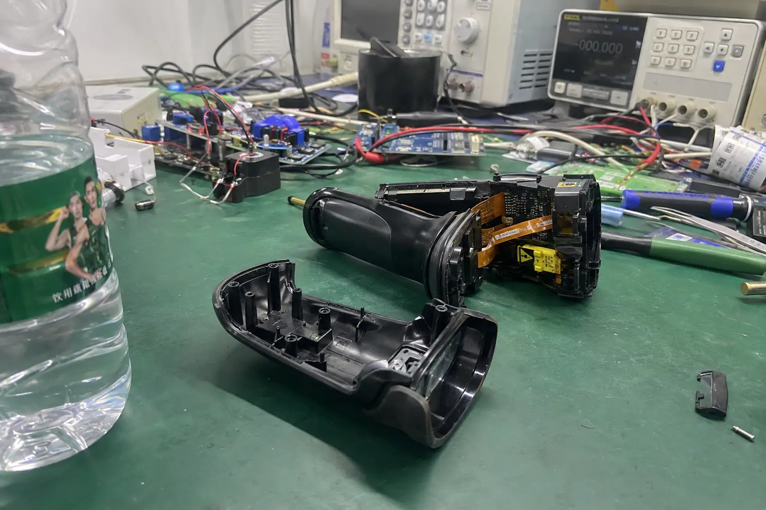
The pilot is going perfectly... for the first twenty minutes. The read range on your new handheld inventory scanner is solid. Then, it starts to shrink. What was reading tags from 2 meters away now struggles at 50cm. The device is hot to the touch, and your application is timing out. The pilot fails, and your "finished" product is suddenly back on the engineering bench, threatening your launch date.
When you choose an RFID reader module for an embedded device, thermal stability is the single most critical factor for reliable performance. Read rate collapse during continuous use is almost always caused by the module's power amplifier overheating1 due to poor PCB thermal design, a problem solved by modules engineered with superior heat dissipation and intelligent power management firmware.
Let's be blunt: this isn't a software bug or an antenna mismatch. It's a fundamental failure of thermal engineering. The cheap RFID module you integrated has no strategy for dissipating the heat it generates during continuous operation. After a few minutes of high-power transmission, the chip overheats, its efficiency plummets, and your read range collapses. It's a predictable, physical failure.
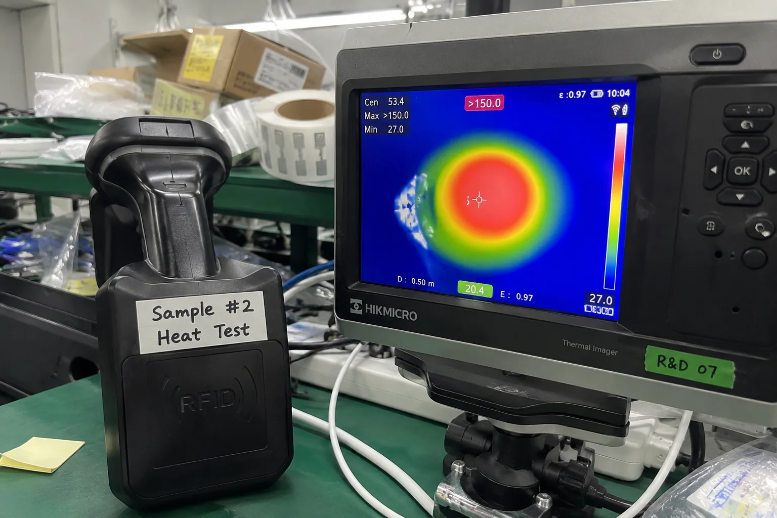
This is one of the most common—and frustrating—failures I see when integrators try to cut corners on core components.
The Core Technical Trap: Chasing Peak Power, Ignoring Thermal Stability
When you first set out to choose an RFID reader module, you're looking at datasheets. You see an impressive small size, a low price, and a claimed 30dBm output power2. It seems perfect for your compact handheld design.
That 30dBm is a "peak" power, achievable for milliseconds in a lab at 25°C. The real spec you need is "thermally stable continuous power," a metric you will never find on a cheap module's datasheet because the number would be embarrassingly low.
The solution is to scrutinize the physical design of the module itself. A module designed for sustained performance looks physically different.
| Feature | Generic "Black Box" Module | Fongwah Engineered Module |
|---|---|---|
| Thermal Design | Minimal PCB copper, no heat sink | Large ground plane, thermal vias, heatsink pads |
| Power Amplifier (PA) | Lowest cost, high heat chip | Low-power architecture, thermally efficient chip |
| Firmware Control | Fixed power, no feedback | Dynamic power adjustment based on temperature |
| Real-world Output | Drops >50% after 15 mins | Stable output for hours of continuous operation |
Hardware Teardown: Behind the Datasheet
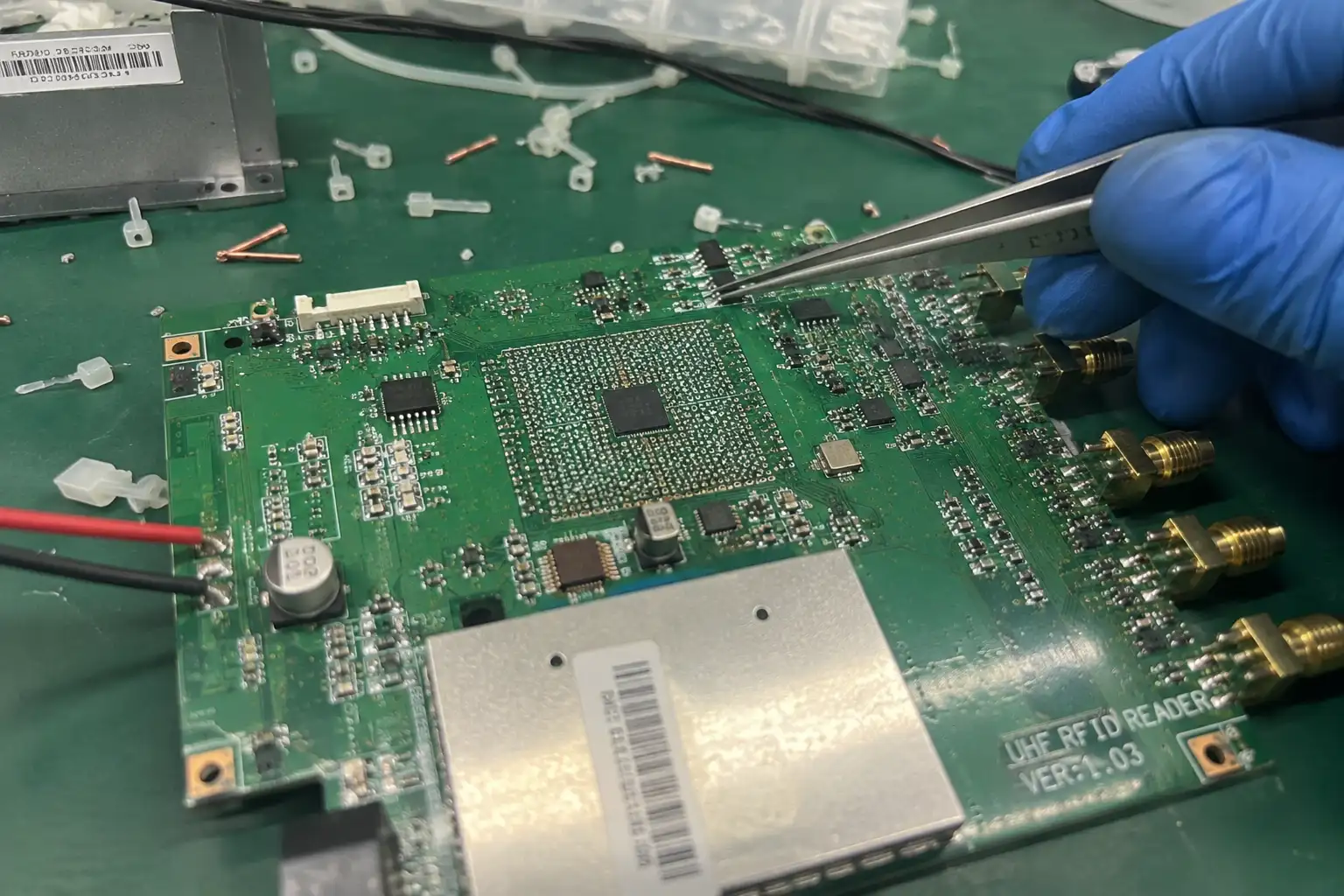
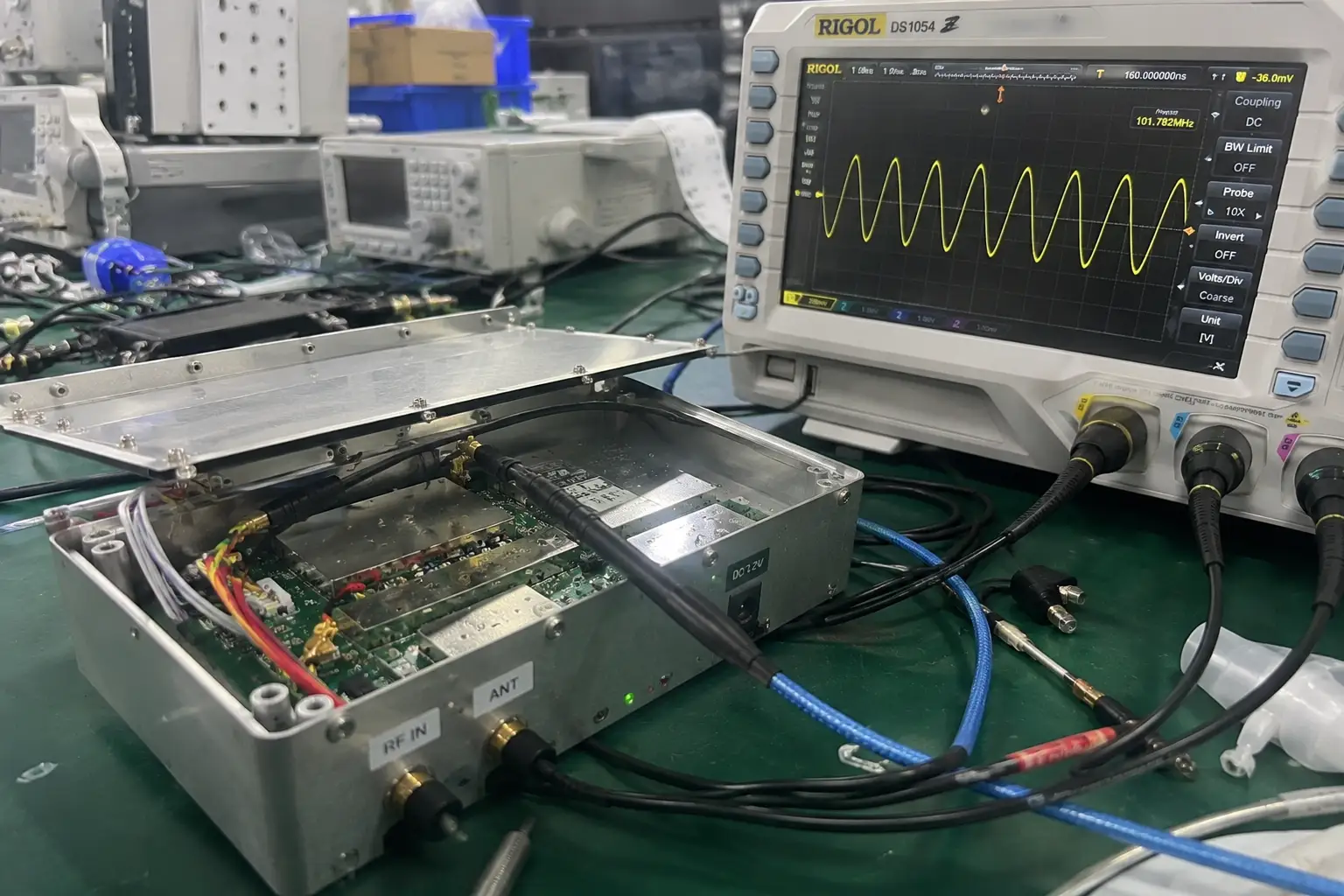
I've spent my career on the factory floor and in the lab, and I've torn down these failed modules. The story is always the same. The power amplifier (PA) is a tiny black square sitting on a PCB with minimal copper around it. It has no escape path for heat. It's an engine with no radiator. These modules are designed for applications like a desktop reader or a smart cabinet that perform one read every few minutes. The duty cycle is low, so the chip has time to cool down3.
You, however, are putting it in a sealed plastic handheld and asking it to run a marathon of continuous inventory scans. It was built for a 10-meter dash.
Our embedded modules are designed with thermal dissipation as a primary feature. We use thick copper pours that act as built-in heat sinks and stitch the PCB layers together with dozens of "thermal vias"—small, plated holes that carry heat away from the PA. When you're evaluating options, look at the physical designs in our Fongwah Embedded RFID Reader Module Catalog; the engineering difference is visible.
Integration & Environment Realities: Firmware is Your Radiator's Fan Control
The second mistake I see is a "brute force" integration approach. The developer gets the SDK, finds the setPower(level) command, and immediately sets it to the maximum value, thinking this will guarantee the best performance.
This "max power" approach actually guarantees thermal failure. A professional integration uses intelligent firmware to get the job done without cooking the hardware.
The solution is to use a module with a sophisticated SDK that allows for dynamic control, not just a blunt "on/off" power setting. Before you choose an RFID reader module, verify its SDK can perform these actions:
- Query PA Temperature: Can your application ask the module for its current operating temperature?
- Set Power Ceilings: Can you programmatically limit the max power to prevent overheating in a hot environment?
- Use Low-Power Sniff Modes: Does the module have a low-power mode to detect tags without running the PA at full blast?
- Dynamic Power Adjustment: Does the firmware automatically reduce power if it senses a critical temperature, preventing a complete shutdown?
A cheap module's SDK will have none of these. A professional one treats them as essential.
Engineer's Insight: What the Specs Don't Tell You
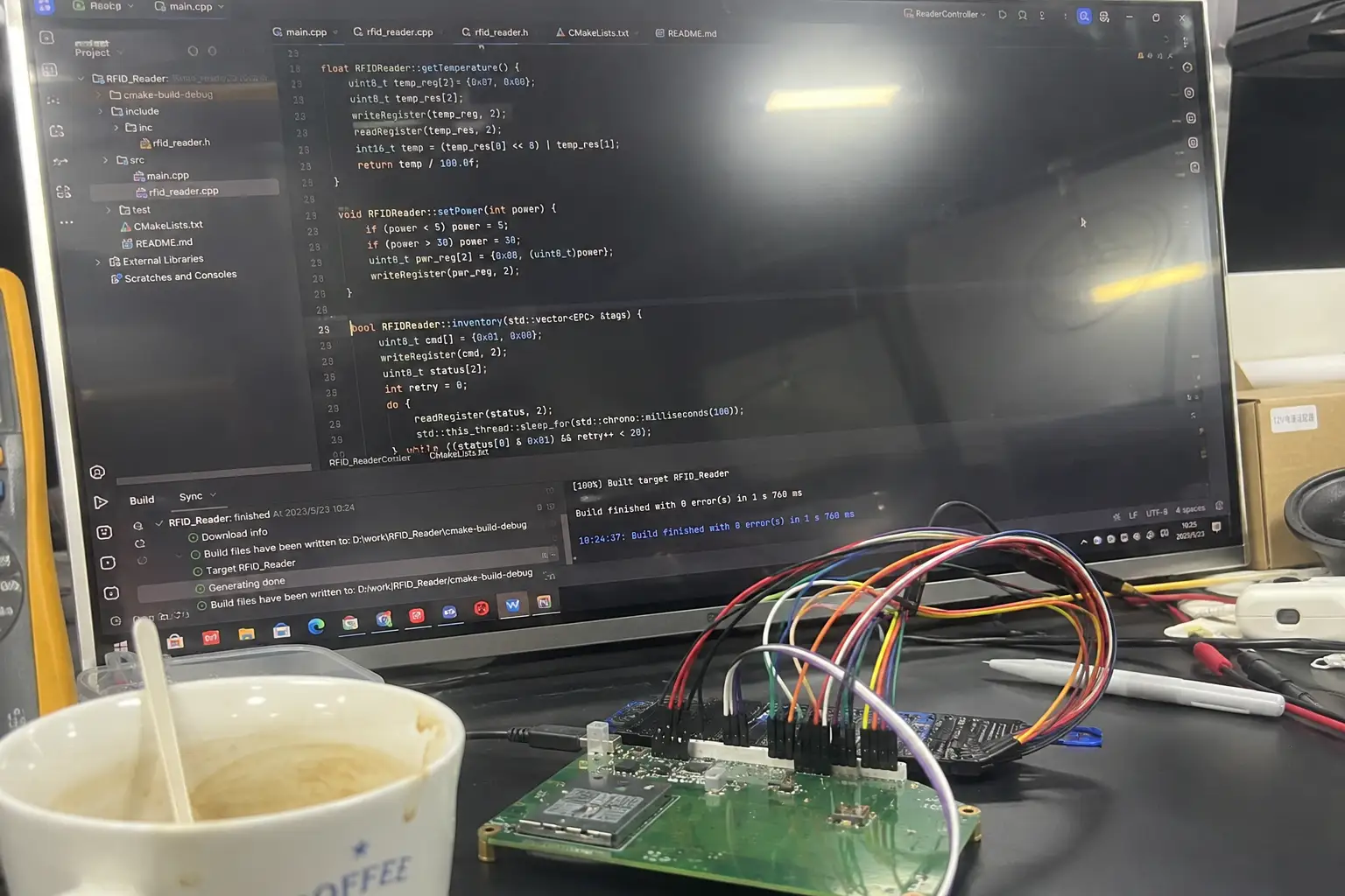
A 'dumb' module forces you to choose between range and stability. A smart one lets you have both. For example, our firmware has advanced logic that's not just for regulatory compliance, but for thermal health. It can detect when it's reading the same tag population over and over in a dense environment and automatically reduce its polling rate and power. This prevents overheating and dramatically extends the battery life of your entire handheld device—a huge selling point for your final product. This level of control is only possible with a deep partnership between hardware and software, the foundation of our Fongwah RFID SDK Integration & Software Support.
Sourcing, Compliance & Risk Mitigation: The True Cost of a "Bargain"
That RFID module was only $30, a real bargain. But now you're facing a full product redesign, a delayed launch, and an unhappy client. The true cost of that "bargain" is now in the tens of thousands of dollars.
The risk of field failure is the most expensive part of any hardware project. Sourcing a core component like an RFID module from a partner who understands and designs for thermal, electrical, and environmental stress is how you de-risk your entire project. A cheap supplier sells you a part in a plastic bag. A true engineering partner helps you design a successful, reliable product.
| Supplier Attribute | "Box Shifter" Supplier | Engineering Partner (Fongwah) |
|---|---|---|
| Thermal Data Provided | None | Full thermal models for simulation |
| Integration Support | Email to a generic sales address | Direct access to firmware/hardware engineers |
| Long-Term Availability | Discontinued without notice | 5+ year lifecycle guarantee |
Conclusion: Choosing Reliability Over Risk
Your choice of an embedded RFID module is not a simple component decision based on a datasheet. It's a strategic choice about the reliability and reputation of your final product. You must look past the "peak power" claims and evaluate the module's ability to sustain that performance in the real world. That ability comes from deliberate, professional thermal engineering.
Stop Debugging Hardware with Software
Are you designing a new handheld device and worried about thermal performance and battery life? Don't wait for the prototype to fail. Send me your design concept and use case. We can provide the thermal data for our modules to help you model performance correctly before you build anything. At Fongwah Technology, we help you engineer failure out of your system from day one. Contact our engineering team for a direct review and quote via the Fongwah Direct Factory RFQ Portal.
Frequently Asked Questions
Q1: SIf we integrate your module into a sealed IP67 handheld housing without active ventilation, how long can it maintain peak 30dBm output before thermal throttling triggers?
Answer: Our modules do not blindly throttle down by massive step-drops. When paired with a proper chassis thermal interface pad linked to your device's internal metal frame, the module sustains its configured RF output indefinitely at typical ambient room temperatures. Under extreme 50°C environments4, our dynamic firmware utilizes micro-adjustments (0.5dBm increments) based on real-time internal thermistor telemetry5, ensuring continuous tracking and avoiding the sudden 50% read-range collapse typical of unmanaged bargain modules.
Q2: How does your module handle impedance mismatches caused by near-field metallic interference or detuned antennas without burning out the power amplifier?
Answer: Our embedded module design incorporates a ruggedized power amplifier (PA) architecture featuring high VSWR (Voltage Standing Wave Ratio) ruggedness. If a customized antenna becomes severely detuned due to proximity to metal or liquid targets, the reflected RF power is effectively dissipated through our massive ground plane layer rather than generating destructive localized hotspots within the PA silicon junction. Furthermore, the firmware detects anomalous current draw from extreme mismatches and proactively protects the RF front-end while remaining operational.
--
---"RFID Read Range Collapse: The Thermal Trap | Fongwah", https://fongwahrfid.net/rfid-module-thermal-throttling/. RF power amplifiers exhibit reduced efficiency and output power as junction temperature increases, a well-documented phenomenon in semiconductor physics that directly impacts transmission performance in continuous-duty applications. Evidence role: mechanism; source type: paper. Supports: RF power amplifier efficiency degrades with increasing junction temperature. Scope note: General RF amplifier behavior; may not specifically address RFID reader modules ↩
"[PDF] Part 15 Update - Federal Communications Commission", https://transition.fcc.gov/oet/ea/presentations/files/may05/New_Policies_Pt._15_SD.pdf. Regulatory bodies such as the FCC and ETSI establish maximum effective radiated power limits for UHF RFID readers, typically in the range of 30-36dBm EIRP depending on frequency band and region, which constrains module design specifications. Evidence role: general_support; source type: government. Supports: Regulatory frameworks establish maximum RFID reader output power limits. ↩
"Electronics Thermal Management - an overview | ScienceDirect Topics", https://www.sciencedirect.com/topics/engineering/electronics-thermal-management. Electronic components operating at low duty cycles experience periodic thermal recovery as heat dissipates during off-periods, with the effectiveness depending on the thermal time constant of the system—the time required for temperature to reach approximately 63% of its steady-state value—which is determined by thermal mass and heat transfer characteristics. Evidence role: mechanism; source type: education. Supports: Intermittent operation with low duty cycles allows components to dissipate accumulated heat. ↩
"Operating temperature - Wikipedia", https://en.wikipedia.org/wiki/Operating_temperature. Electronic equipment is commonly classified by operating temperature ranges: commercial (0°C to 70°C), industrial (-40°C to 85°C), and military (-55°C to 125°C), with 50°C ambient representing a challenging condition near the upper limit of commercial specifications that significantly reduces available thermal headroom for heat-generating components. Evidence role: general_support; source type: education. Supports: 50°C ambient temperature represents the upper limit of typical commercial operating ranges. ↩
"Thermistor - an overview | ScienceDirect Topics", https://www.sciencedirect.com/topics/engineering/thermistor. A thermistor is a temperature-dependent resistor, typically with a negative temperature coefficient (NTC), that exhibits predictable resistance changes with temperature and is commonly integrated into electronic systems for thermal monitoring, providing analog feedback for temperature-based control algorithms. Evidence role: definition; source type: encyclopedia. Supports: Thermistors are temperature-sensitive resistors used for thermal monitoring. ↩