You stick a standard tag on a steel pipe and the signal disappears. For anyone deploying RFID tags on metal surfaces — pipework, racking, vehicle chassis, tools — that two-cent sticker can take down an entire tracking system. The cause is physics, not price: metal detunes the antenna and absorbs the radio energy the tag needs to reply. We have watched teams pay good money for a label that looks rugged, then watch it go dark on a steel beam by lunchtime — the metal does not care what you paid, detuning is detuning. In our industrial testing, standard wet inlays and thin labels simply stopped responding the moment they touched steel, while only hard-shell PCB tags and flexible on-metal RFID tags — built with a specialized ferrite layer or a thick dielectric spacer — held a readable signal. If you are specifying tags for conductive assets, the sections below explain what fails, why it happens, and which constructions actually survive in the field. By the end, you should be able to read a datasheet critically, pick a construction for your specific asset, and specify a mount that stays attached through a Canadian winter.
Why do standard RFID tags fail on metal?
- Standard paper and PET inlays read as effectively unreadable on steel; only PCB (FR4) or ceramic-construction tags held usable range (about 650 cm and 400 cm in our bench setup).
- Metal detunes the antenna by shifting its resonant frequency away from the 860–960 MHz reader band through eddy currents and changed capacitance.
- Adhesive failure — not the chip — is the main cause of tag loss on metal; rigid bonds shear under thermal expansion cycling from −20 °C to +60 °C.
- Datasheet read ranges overstate real performance: a 10 m-rated on-metal tag dropped from 9 m at 90° to 2 m at 45° because of patch-antenna directionality and multipath.
- Test on the actual asset, not the spec sheet; the size and shape of the metal object change the antenna itself.
If you are scoping a full deployment, our breakdown of the four core components of an industrial RFID system covers readers, antennas, and middleware before you commit to a single tag type.
Why Do Standard Inlays Stop Reading on Steel?
You assume an on-metal RFID tag that reads at 10 m in free air will read on a forklift. You place it on the metal chassis, and the reader goes blind.
The metal surface acts as a ground plane that disrupts the tag's electromagnetic field. Without a specialized spacer or ferrite shield, the metal induces eddy currents that cancel the tag's response, making it invisible to the reader. These tags operate under the EPC Gen2 (ISO 18000-6C) air-interface standard for UHF RFID, which GS1 defines for the 860–930 MHz band (GS1 EPC UHF Gen2 Air Interface Protocol). When surrounding metal shifts that band, the reader and tag stop agreeing on a frequency, and the link collapses.
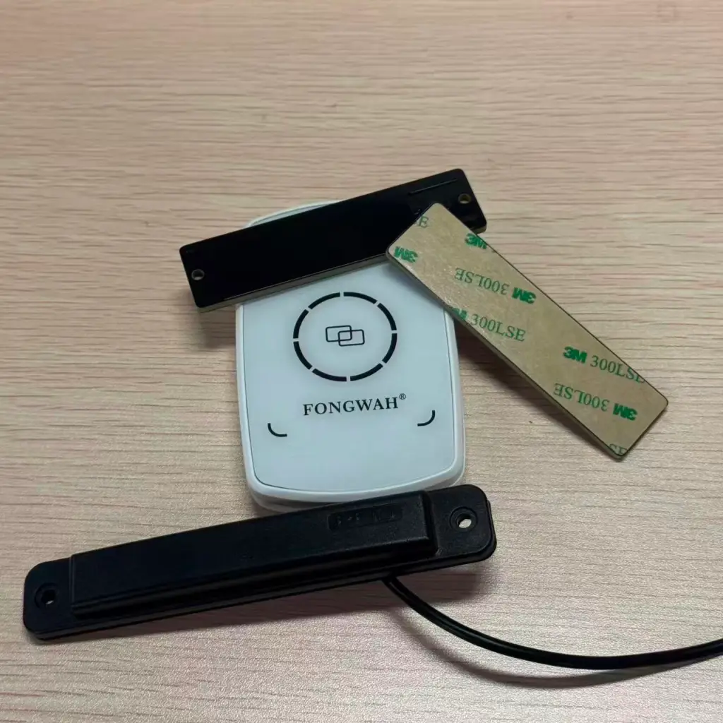
The Physics of Detuning
An RFID tag is a tuned circuit. Its antenna is cut and matched to a specific frequency, usually around 860–960 MHz, and it relies on impedance matching to harvest energy from the reader's field. The chip itself presents a fixed impedance; the antenna must transform the free-space wave into that impedance for power transfer to work. Metal changes the environment right next to the antenna. It alters the local capacitance and, through eddy currents, shifts the tag's resonant frequency away from the reader's frequency.
It is like tuning a radio station while someone keeps turning the dial.
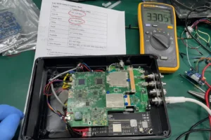
We measured this directly on the bench. In our bench test, we evaluated 10 samples of each construction using a fixed UHF reader at 30 dBm, with every tag placed directly on a 3 mm steel plate in line-of-sight. We recorded the maximum read distance before the tag became unreadable. We also tried several "semi-metal" tags with a thin foam layer; they failed too. The only constructions that held a signal used a ceramic core or a PCB (Printed Circuit Board) backing, because those materials supply the dielectric constant needed to form a buffer zone that keeps the metal from killing the field.
Bench test — maximum read distance with each tag placed directly on a 3 mm steel plate, 30 dBm reader, line-of-sight:
| Tag Construction | Spacer Material | On-Metal Result | Why it Happened |
|---|---|---|---|
| Standard Paper Inlay | None (Adhesive only) | Unreadable (≈0 cm) | Complete signal absorption and detuning. |
| Thin Foam Label | 0.5 mm PET Foam | ~15 cm | Spacer was too thin to prevent interference. |
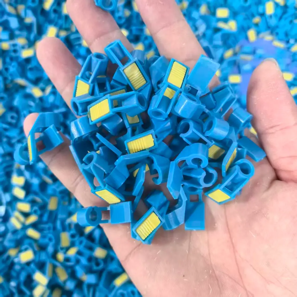
| PCB Hard Tag | FR4 Board | ~650 cm | The board acts as a strong dielectric barrier. |
| Ceramic Tag | Ceramic Block | ~400 cm | High dielectric constant enables small size but good range. |
The numbers describe our bench setup, not a universal law — but the pattern is consistent, and it points to two fixes. The first is physical separation: lift the antenna far enough off the metal that the eddy currents weaken. The second is a high-permeability material such as ferrite, which bends the magnetic field lines away from the metal and suppresses the induced currents. Both approaches appear in real metal-mount RFID tags, often together. Ferrite's high permeability short-circuits the magnetic field that would otherwise drive eddy currents in the steel, which is why a thin flexible on-metal label can work where a bare inlay cannot. This mechanism is backed by peer-reviewed studies on ferrite shielding, which show that inserting a ferrite sheet between the tag and the metal suppresses the induced eddy currents. For the shielding side, see how ferrite and miniaturization interact in compact tag designs. For background on how passive tags are built, see how passive UHF tags work.
Adhesives and Thermal Stress: Where Rigid Tags Fail
A tag reads perfectly on day one. A month later you find it on the concrete floor and the asset is lost again. For RFID tags on metal, the signal may still be perfect — it is the bond that fails.
Metal expands and contracts sharply with temperature changes in a warehouse or yard. A rigid tag paired with standard aggressive glue cannot flex with the substrate, so the bond shears and the tag pops off. This failure mode is easy to miss in a pilot, because pilots rarely run long enough to see a seasonal temperature swing.
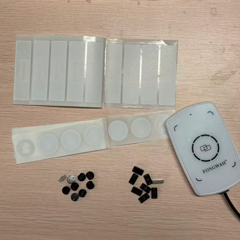
Shear Stress at the Bond Line
In our field inspections we have found entire batches of asset tags detached from metal surfaces — on a fleet of rental trailers returned after a winter outdoors — with the root cause traced to the adhesive rather than the chip. We have pulled those tags off cold steel with our own hands — the spec sheet never lists "gone by spring" as a failure mode, but the field does, and it is the one that actually costs you assets. Here is what happens at the bond line: We ran tags in a thermal chamber, cycling temperature from −20 °C to +60 °C to mimic a typical Canadian winter and summer. Metal moves during those cycles: a steel beam 10 m long can expand by several millimeters. If both the tag and its glue are rigid, something has to give — and it is usually the adhesive bond.
Budget on-metal tags use standard transfer tape that dries out and turns brittle. In our cycling test, three of the budget on-metal tags fell off after just 50 thermal cycles. The tags that survived used 3M's VHB acrylic foam tape or epoxy.
The foam tape matters because it is viscoelastic: it can flow and stretch, so when the metal expands the foam absorbs the movement instead of passing the stress through to the tag. VHB acrylic foam also conforms to slightly uneven surfaces and keeps its bond across a wide temperature range, which is why it is the default for outdoor yard assets. Epoxy is the stronger choice when the tag must survive sustained heat, washdown, or chemical exposure — it cures into a rigid, permanent joint. In cold-chain and autoclave environments we have seen standard foam tapes lose grip within a season; only cured epoxy or a mechanical fastener held. For permanent assets we also recommend mechanical fixation. Screws or rivets do not fail with heat. If you are tracking metal pallets that enter ovens or freezers, do not trust a sticker; specify a drilled or riveted mount, or a tag that is molded for screw holes.
Mounting Recommendations for Longevity
- Indoor Office: Foam tape is acceptable.
- Outdoor Yard: VHB tape or epoxy.
- Industrial Processing: Rivets or screws only.
Those mounting rules settle the mechanical side. For a deeper comparison of tag technologies and power sources, see our guide to active vs. passive RFID for industrial asset tracking.
Spec Sheets vs. the Warehouse Floor: Orientation Kills Read Range
You buy a tag because the datasheet promises a 12-meter read range. You install it and you barely get 4 m.
Lab tests are run in anechoic chambers with the tag floating in free space or bolted perfectly to a metal plate. On a real warehouse floor, reflections, nearby metal, and reader orientation cut the usable distance dramatically — which is why on-metal performance is set by the mounting surface and the read angle, not the brochure.
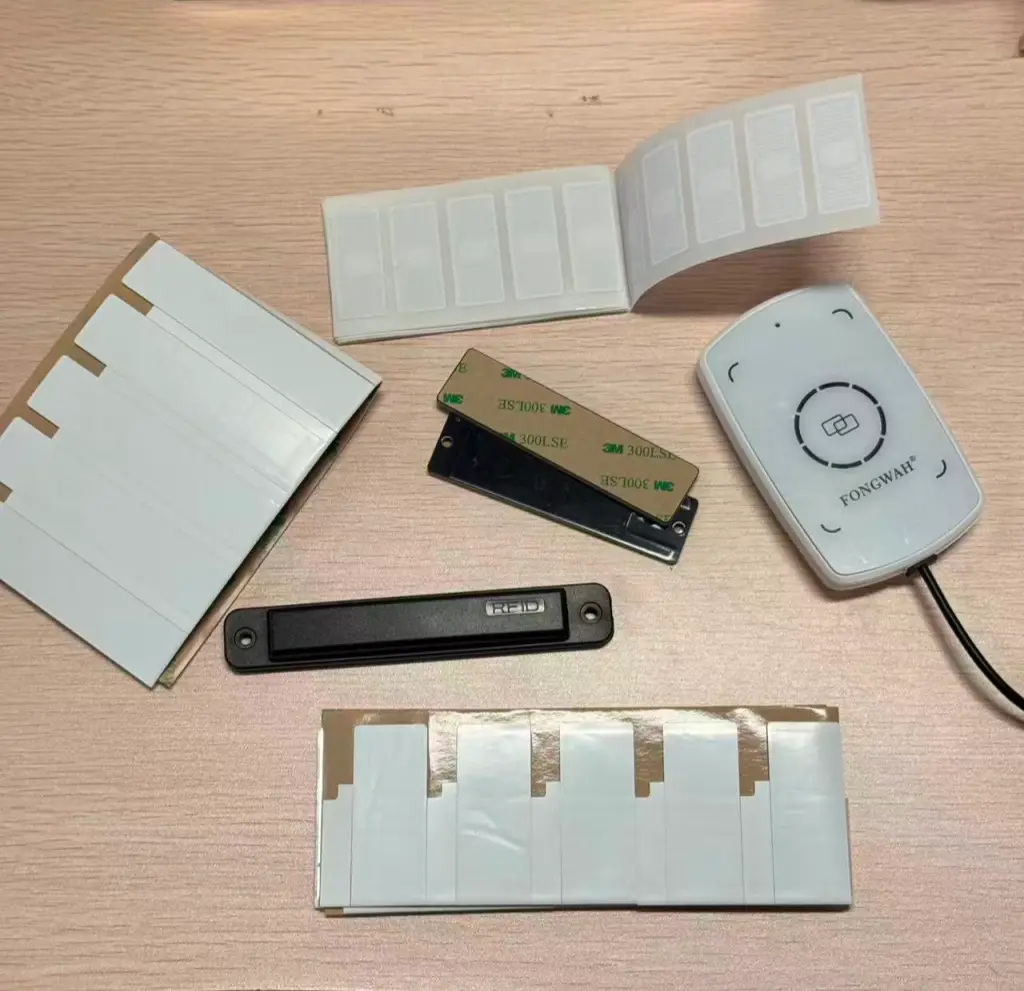
Orientation and the "Flashlight Beam" Problem
Metal surfaces reflect radio waves and create multipath interference. Sometimes the reflections combine to help you; sometimes they cancel out and form null spots or dead zones. This is why a tag can read perfectly at one position on a rack and vanish two bays over. The RAIN RFID Alliance's Lessons Learned from the Field compendium lists this as one of the most common causes of missed reads in real deployments: large metal surfaces inside the read zone, plus direction-sensitive tags.
We tested a popular on-metal tag rated at 10 m. With the reader held directly perpendicular — 90 degrees — to the tag, we measured 9 m. Walk to the side at a 45-degree angle and the range collapsed to 2 m.
Antenna geometry explains the collapse: Many on-metal RFID tags use a patch antenna, which throws energy in a narrow cone like a flashlight beam; step outside the beam and you lose the read. A standard dipole tag — the floppy sticker — has a doughnut-shaped field and reads from many angles, but dipoles are exactly the constructions that fail on metal. That is the trade-off: on-metal tags are usually directional. If a forklift driver approaches a tagged metal bin from a sharp angle, he will miss it. Tags with a 3D antenna structure or cross-polarization held up better in our real-environment checks, because their fields are less dependent on a single perfect angle.
The size of the metal object also matters, and it is the part most buyers overlook. A tag tuned for a large shipping container performs poorly on a small tool handle, because the metal object becomes part of the antenna — too small and the antenna is incomplete, so the tuning the manufacturer measured no longer applies. A practical test is to walk the reader around the asset at several angles and repeat the pass three times; if any angle or pass misses, the tag is not field-ready. Before you standardize, test the tag on the actual asset, at the angles your readers will really use. For tuning guidance, see our optimizing UHF read range on metal guide, which covers spacers, polarization, and placement in detail.
How to Specify the Right On-Metal Tag
Pulling the three failure modes together, the selection decision comes down to surface, environment, and read geometry. The quick reference below maps common assets to a starting point; always confirm with an on-asset test.
| Asset Type | Recommended Construction | Mounting |
|---|---|---|
| Steel pipework, racking | PCB hard tag or ceramic | VHB tape / screw |
| Metal bins, totes | PCB hard tag (patch or 3D antenna) | VHB tape / rivet |
| Outdoor vehicles, trailers | Ceramic or ruggedized PCB | Rivet / screw |
| Small tools, handles | Mini ceramic or 3D-antenna tag | Epoxy / screw |
| Oven / freezer pallets | High-temp ceramic | Mechanical only |
Conclusion
Standard labels and cheap adhesives fail on metal, but the failure follows a pattern — detuning, adhesive shear, and orientation, in that order. Use tuned PCB or ceramic tags, thick foam or ferrite spacers, and industrial bonding — foam tape outdoors, rivets or screws in processing — to get reliable reads. Above all, treat the datasheet as a best case and verify range on the real asset and the real approach angle, because for RFID tags on metal the metal object itself becomes part of the antenna. We have sat in too many post-mortems where a tag "passed the pilot" and then vanished on the floor — so before you standardize, run it on your own metal at your own angle; the datasheet is a best case, and the warehouse floor is the final exam.
If your rollout depends on hitting a specific read distance, start from our UHF read-range optimization guide and validate the tag on the asset before you buy in volume.
The bench and field test data cited throughout this article were produced by the Fongwah RFID engineering laboratory, using the on-asset measurement setups described above. If you are scoping a metal-mount rollout and want our team to validate a tag on your specific assets, reach out to the Fongwah RFID engineering lab.
Free sample evaluation. Need to put our on-metal tags against your own steel, pipework, or chassis? Fongwah offers free sample evaluations — up to 30 pieces — for engineers and system integrators. You cover the inbound shipping; we cover the tags and the datasheets. Contact our team to request your test kit.